

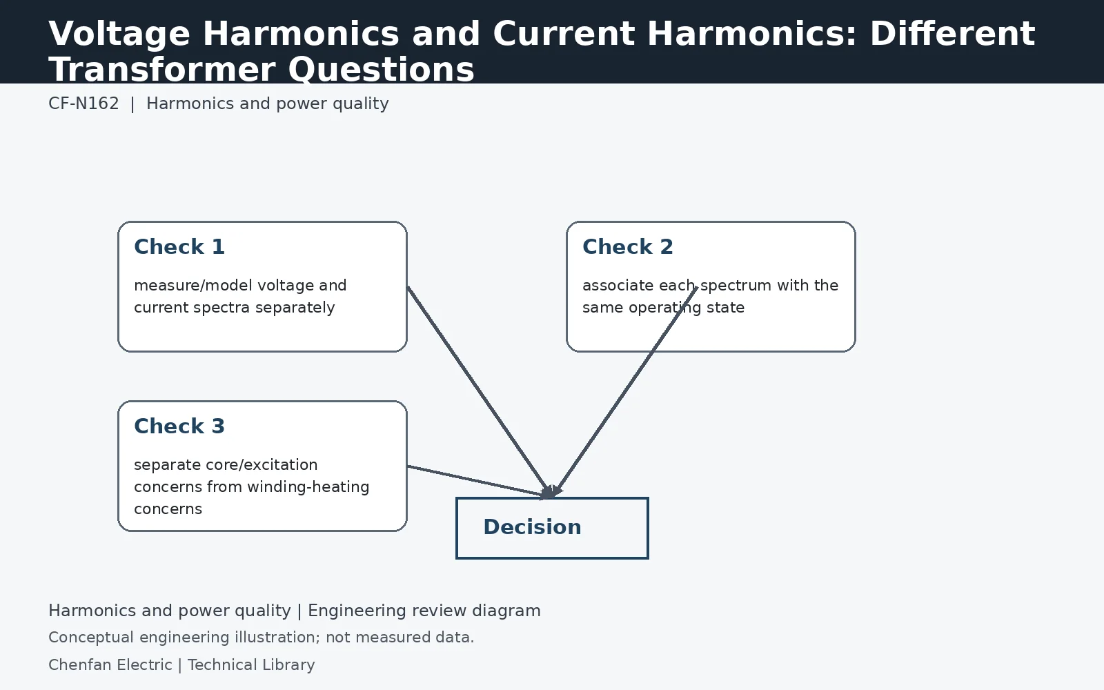
Voltage harmonics and current harmonics stress a transformer through different mechanisms. Current harmonics primarily increase winding and stray losses, while voltage distortion changes flux waveform and can raise core loss or excitation. A study should therefore retain both the bus voltage spectrum and load current spectrum; a low current THD does not prove the applied voltage waveform is benign, and vice versa.
Voltage harmonics enter the flux through integration
Ignoring the winding voltage drop for a first approximation, flux linkage follows the time integral of applied voltage. For a sinusoidal component at harmonic order h, its flux contribution is proportional to Vh/(h f1). A fifth-harmonic voltage equal to 5% of the fundamental therefore gives a flux-component amplitude near 1% of the fundamental in this simplified relation. That is not a core-loss prediction: waveform shape, material behavior and the resulting excitation current still require assessment.
Current harmonics raise more than DC-resistance loss
The sum of squared RMS components determines basic resistive heating when resistance is treated as constant. At higher frequencies, skin and proximity effects and leakage-flux-related losses can increase the effective loss contribution. The transformer loss model therefore needs more detail than multiplying total RMS current squared by a room-temperature winding resistance. Different winding arrangements and conductor dimensions can respond differently to the same spectrum, so a load-side THD figure cannot establish a universal derating factor.
Measure voltage and current at a common reference point
Harmonic current interacting with network impedance contributes to bus-voltage distortion, while background voltage harmonics can exist independently of the local load. Retain simultaneous voltage and current spectra, the measurement location and the source configuration. A before-and-after load comparison can help distinguish causes, but does not replace a network model where resonances or several harmonic sources interact. Procurement should state the applied-voltage environment as well as the load-current duty.
Technical reference framework
[1] IEEE C57.110-2018 — Transformer capability with nonsinusoidal load currents.
[2] IEC 60076-1:2011 — Power transformers, General.