

Core flux follows voltage-time area per turn. For a periodic transformer state, the net induced volt-seconds over a complete cycle must return the flux to its starting value. Equal positive and negative voltage peaks do not establish that balance; their durations and shapes matter as well.
Use the integral before using a waveform factor
With a consistent polarity convention, e(t) = N dPhi/dt. Over an interval, Delta Phi = integral(e dt)/N. This fundamental relationship applies to the induced winding voltage; the familiar sinusoidal coefficient is a special case, not a substitute for integrating an arbitrary waveform. [1]
For a uniform average section, Delta B = integral(e dt)/(N A_net). State whether the result is a peak-to-peak excursion or an offset from an initial value. The integral alone does not establish the absolute initial flux.
Terminal voltage is an approximation to induced voltage only to the extent that winding and leakage-related drops can be neglected for the question. During strong current transients, retain the circuit terms rather than treating every measured terminal volt-second as mutual flux change.
Compare pulse areas explicitly
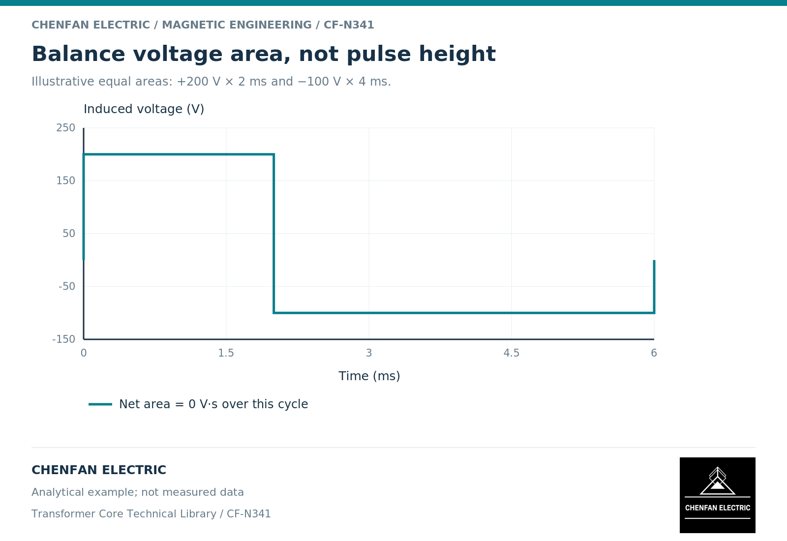
Consider an illustrative winding with 100 turns. A positive induced pulse of 200 volts for 2 milliseconds contributes 0.4 volt-second and a flux change of 0.004 weber. A negative pulse of -100 volts for 4 milliseconds contributes -0.4 volt-second and returns that idealized change to zero.
The voltage peaks are unequal, but the areas balance. Conversely, equal peaks of plus and minus 200 volts do not balance if their durations are 2 and 1.9 milliseconds. The remaining 0.02 volt-second corresponds to 0.0002 weber per cycle in this ideal arithmetic example.
A real converter-transformer circuit may respond through control action, resistance drops or nonlinear current before such drift continues indefinitely. The calculation identifies an imbalance; it is not a prediction of unlimited physical flux growth.
Keep balance separate from maximum excursion
Zero net area over a cycle does not guarantee an acceptable peak flux. A balanced pair of large pulse areas can still drive a large excursion. The starting residual state can also shift the entire trajectory toward one nonlinear region.
Similarly, a low root-mean-square voltage does not necessarily imply a small maximum integral. The waveform’s time distribution matters. A review should retain the cumulative integral through the cycle, not only the final net value.
Transformer-design guidance for switched excitation discusses volt-second imbalance and flux walking. [2] Its circuit examples should be used for the mechanism, not as numerical design rules for utility-frequency equipment.
Handover a waveform-area check
| Quantity | Required interpretation |
|---|---|
| Positive and negative area | Signed induced volt-seconds over defined intervals |
| Net cycle area | Change in flux between cycle boundaries |
| Maximum cumulative area | Largest excursion relative to the starting state |
| Initial flux | Measured estimate or stated assumption |
| Turns and net area | Conversion into flux and average density |
The review should identify the operating modes included: steady operation, startup, modulation changes and any specified abnormal duty. A waveform balanced in one mode may not be balanced in another.
The useful result is a traceable integral with units, polarity and assumptions. It allows the transformer designer to evaluate the magnetic excursion and gives the core manufacturer a defined area and branch-flux requirement. It is more informative than a statement that the waveform “looks symmetrical” or that its root-mean-square voltage matches the nameplate.
References
[1] Lloyd Dixon / Texas Instruments. Magnetics Design 1 – Introduction and Basic Magnetics.
[2] Lloyd Dixon / Texas Instruments. Magnetics Design 4 – Power Transformer Design.