

A shipboard transformer footprint should include the space needed for connections, cooling, inspection and replacement. Body dimensions alone do not establish a workable installation. A compact transformer can become difficult to maintain or impossible to remove after the surrounding vessel structure and services are complete. Freeze the service envelope with the electrical and compartment design.
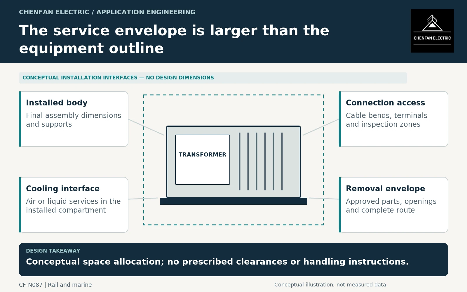
Distinguish occupied space from usable access
The equipment outline describes what is installed, not how it is serviced. Identify terminal approach directions, removable covers, accessible sensors and cooling-equipment maintenance points. A front-access claim should state exactly which functions are accessible from the front.
IEC 60092-303 addresses shipboard transformer requirements within its scope. It does not approve a particular compartment layout or replacement route. [1]
The design should use supplier-supported clearances and access requirements for the actual equipment. This article does not prescribe universal marine transformer spacing, cable-bend dimensions or work procedures.
Coordinate cooling and cable space early
For air-cooled equipment, show inlet and outlet paths and the conditions supplied by the compartment ventilation system. Warm-air recirculation can make a nominally adequate room arrangement unsuitable at the transformer interface.
For liquid-cooled equipment, identify service connections, valves or other approved separation boundaries and the access required for maintenance. The cooling arrangement may occupy space outside the main transformer body.
General transformer application guidance addresses equipment operating conditions, while specialized shipboard requirements and the vessel design determine the installation boundaries. [2]
Cable routes should preserve terminal access and the supported connection geometry. A drawing that fits the transformer but leaves no route for the actual cables is not a coordinated installation. External supports and equipment-interface loads also need agreement rather than being assigned implicitly to the transformer terminals.
Trace removal through the completed vessel
Identify whether replacement uses the complete assembly or supplier-approved separable components. Record dimensions and masses for the removal configuration, not only the installed configuration.
The route should include doors, hatches, turns, deck openings and permanent services. A transformer installed before a deck or bulkhead was closed may not have the same route available during service.
A useful removal record identifies the equipment envelope, clear openings, removable obstructions, intermediate interfaces and external transfer point. It is a planning document, not a lifting procedure. Handling methods and structural capacities require the vessel’s approved engineering.
The cited fittings guidance addresses accessories of liquid-immersed power transformers and reactors, within its defined scope; it does not establish that every proposed disassembly or handling boundary is permitted. [3] Obtain the supplier’s actual separation and preservation requirements.
Accept maintainability as a defined feature
The purchasing package should include a coordinated service-envelope drawing, connection arrangement, cooling interface and removal route. Link all dimensions to the final equipment revision.
Acceptance should check that later cable trays, piping or ventilation changes have not consumed the reserved space. A small accessory relocation can affect access even when the overall transformer dimensions remain unchanged.
Keep maintainability claims narrow. “Compact” describes size; “serviceable in place” and “replaceable through the stated route” require different evidence. Neither should be inferred from the other.
The practical outcome is a transformer installation that fits not only on delivery day but throughout its service life. Reserving the correct access and removal boundaries early is more reliable than expecting future maintenance teams to solve a blocked route inside an operating vessel.
Core procurement checkpoint: State which dimensions govern receiving and assembly
For shipboard access, distinguish packed dimensions, delivered core dimensions and the space needed for winding insertion or yoke handling. The transformer manufacturer should approve any sectional delivery or reassembly plan. A pre-stacked core is not automatically ready for arbitrary disassembly, and a dimensional drawing alone does not prove that the completed transformer can be replaced through the vessel’s service route.
For the core enquiry: Delivery and packed envelopes; approved assembly sequence; packet labels; clamp boundary; lifting and receiving responsibilities.