

A marine distribution transformer’s neutral arrangement should follow the ship’s approved grounding, protection and continuity philosophy. The transformer connection is one part of that system. An unearthed or impedance-grounded description does not automatically establish how every fault is handled, and it should not be used to imply that continued operation is always acceptable after a first fault.
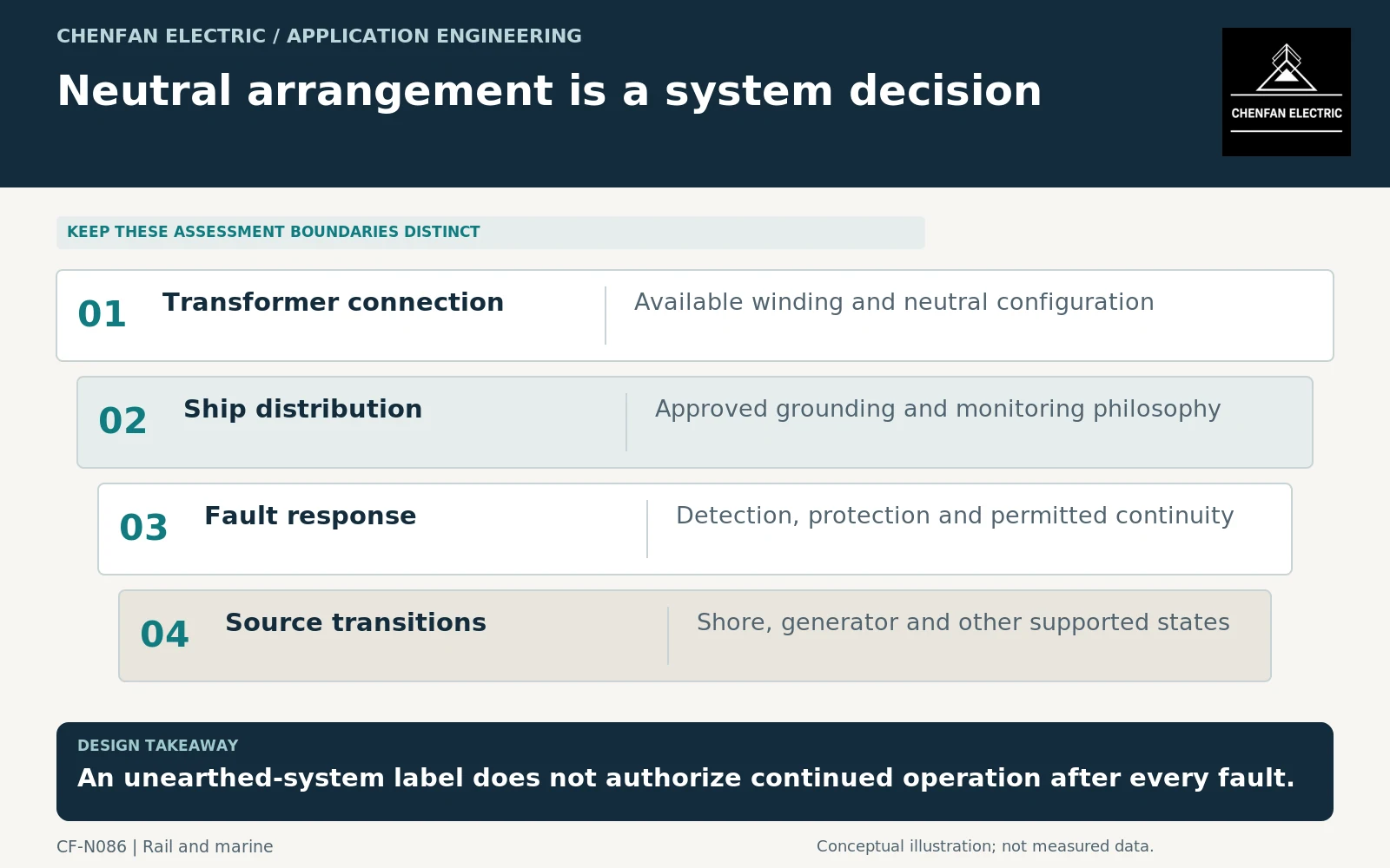
Define the ship-network arrangement explicitly
Identify the supplied voltage system, winding connection, available neutral and the intended grounding arrangement. State which loads are connected and whether source transitions change the configuration.
IEC 60092-303:2023 addresses shipboard transformers within its defined scope. It does not replace the complete ship electrical-system design or the applicable classification and project requirements. [1]
The enquiry should distinguish a transformer that makes a neutral available from the system decision about how that neutral is used. Those are different responsibilities and should be documented separately.
Separate continuity objectives from fault assumptions
Some marine systems are designed with continuity considerations that differ from ordinary terrestrial distribution. The actual fault response depends on grounding, system capacitance, monitoring, protection and connected equipment. A general label cannot establish all of those conditions.
The responsible electrical designer should define what is detected, which faults require disconnection and what operation is permitted while a condition is investigated. This article does not provide protection settings or instructions for continuing operation after an earth fault.
General transformer application guidance addresses connections and operating behavior, while neutral-grounding resistor requirements apply only where that equipment is actually part of the design. [2] [3]
A resistor standard is not a complete grounding-system design. The selected resistance, duty and protective response require project-specific analysis and coordination.
Review every source state
| Source or network state | Required agreement |
|---|---|
| Normal generator supply | Grounding reference and protection behavior |
| Shore-connected operation | Coordination across the shore-ship boundary |
| Alternate-source transfer | Which neutral and source connections remain present? |
| Split or combined buses | Changes to fault paths and monitoring coverage |
| Equipment unavailable | Permitted continuity and restrictions |
A grounding arrangement suitable in one state may need coordinated switching or other design provisions in another. Do not infer those provisions from a generic transformer connection diagram.
Where shore power is involved, the high-voltage shore-connection framework has its own scope. It should not be used as a blanket requirement for every shipboard circuit or low-voltage connection. [4]
Make the transformer offer match the system philosophy
The transformer schedule should state winding connections, neutral terminal requirements, insulation duties and the relevant operating cases. Ask the supplier to identify any restrictions or assumptions about grounding and fault exposure.
The system integrator should own the complete grounding and protection claim, supported by the necessary studies and approved drawings. Equipment test evidence should retain its actual scope rather than being described as proof of shipwide fault continuity.
Acceptance should verify that the delivered transformer, neutral accessories and source-transition arrangement match the approved design. Later changes to shore connection or bus configuration should trigger review where they alter the grounding boundary.
The useful specification states how the transformer participates in a defined marine distribution system. It avoids both prescribing one neutral arrangement for every vessel and making an unsafe blanket claim that a particular arrangement renders first faults harmless.
Core procurement checkpoint: Do not confuse core bonding with system neutral earthing
A marine transformer’s core and structural bonding arrangement belongs in its approved assembly documentation; the ship’s neutral arrangement is a separate system-design decision. The core supplier should follow the released drawing for any included interfaces without prescribing the vessel’s earthing scheme. A core or material certificate does not establish continuity of service following a shipboard fault.
For the core enquiry: Approved core/bonding interface drawing; included components; material records; owner of neutral-earthing and ship-system qualification.