

A transformer layout inside or beside a battery energy storage system (BESS) container must reserve space for connections, cooling, inspection and eventual removal—not just the equipment body. A compact arrangement can be electrically acceptable yet difficult to service or impossible to replace without dismantling unrelated equipment. Treat the maintenance envelope as an input before container dimensions and access openings are frozen.
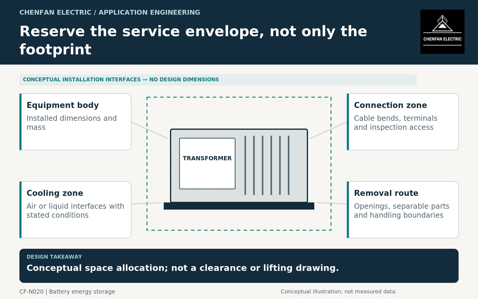
Separate four different space requirements
The installed footprint describes the equipment’s occupied area. Electrical clearances, service access and removal space are additional requirements with different purposes. They should not be compressed into one unexplained perimeter dimension.
Identify which components require routine inspection and which may require replacement. Cable terminations, cooling equipment, sensors and access covers can impose different approach directions. An opening that allows visual inspection may not permit tool access or component removal.
General transformer requirements provide an equipment framework, but they do not certify a project-specific container layout. The approved installation arrangement must address the complete assembly and its interfaces. [1]
Assign cooling responsibility across the enclosure
For a ventilated installation, define the air conditions at the transformer’s cooling inlet, not merely the outdoor weather value. Recirculation, nearby heat sources, filters and enclosure restrictions can change the actual inlet condition.
For a liquid-cooled arrangement, identify the supplied medium, temperatures, flow conditions, pressure boundaries and failure response. The cited fan and insulating-liquid-to-water heat-exchanger standards concern liquid-immersed power transformers and reactors, but compliance by an individual fan or heat exchanger does not prove the performance of the entire container. [2] [3]
| Interface | Required drawing or agreement |
|---|---|
| Cooling air | Inlet, outlet, recirculation and service-filter arrangement |
| Liquid services | Connection locations, operating boundaries and isolation ownership |
| Cables | Bend envelopes, terminal access and supporting structure |
| Monitoring | Accessible devices and communication connection points |
| Replacement | Removal envelope and retained access openings |
Avoid specifying an ingress classification without reviewing its interaction with ventilation and heat rejection. IEC 60529 classifies enclosure protection; it is not a thermal-performance approval. [4]
Plan for the heaviest realistic replacement item
Determine whether the transformer is removed as one assembly or as supplier-approved separable components. Record the relevant masses and dimensions for the removal configuration. An installed overall mass alone does not describe the handling interface.
Check the complete route from the operating position to an external transfer point. Doors, roof panels, cable trays, adjacent containers and permanent pipework can become constraints after installation. Identify which items may be removed and which must remain in place during service.
This review should produce interface dimensions and responsibilities, not an improvised lifting procedure. Handling methods, equipment and structural capacity require a separate approved plan based on the actual assembly and site.
Freeze a service-access drawing with the electrical design
Require a coordinated drawing showing body dimensions, terminal zones, cooling paths, inspection access and the removal envelope. Link it to the equipment revision and container arrangement. Supplier and integrator comments should be closed before manufacturing changes become expensive.
Keep maintainability claims specific. “Front access” should identify which functions are accessible from the front and which still require side or rear access. “Replaceable” should identify the required opening and the configuration in which replacement occurs.
The completed layout is one in which electrical interfaces, thermal conditions and maintenance tasks can coexist. Saving a small amount of floor area is not a benefit if the resulting arrangement depends on blocked cooling or an unavailable replacement route.
Core procurement checkpoint: State the delivered assembly envelope
For a containerized layout, the core quotation should distinguish loose laminations, pre-stacked packets and an assembled core. Each has a different receiving and assembly interface. Ask the transformer manufacturer to confirm the envelope for inserting windings, handling yokes and fitting any clamps. A compact core drawing does not establish that the completed transformer can be maintained through the container opening.
For the core enquiry: Delivery form; assembled and handling dimensions; included clamps; winding-insertion sequence; packaging and receiving constraints.