

A transformer in a semiconductor facility should be represented accurately in voltage-sag studies, but it should not be presented as a universal cure for upstream voltage disturbances. The study needs source conditions, transformer and cable data, load tolerance and any mitigation system. Equipment isolation, voltage transformation and energy support are different functions with different evidence requirements.
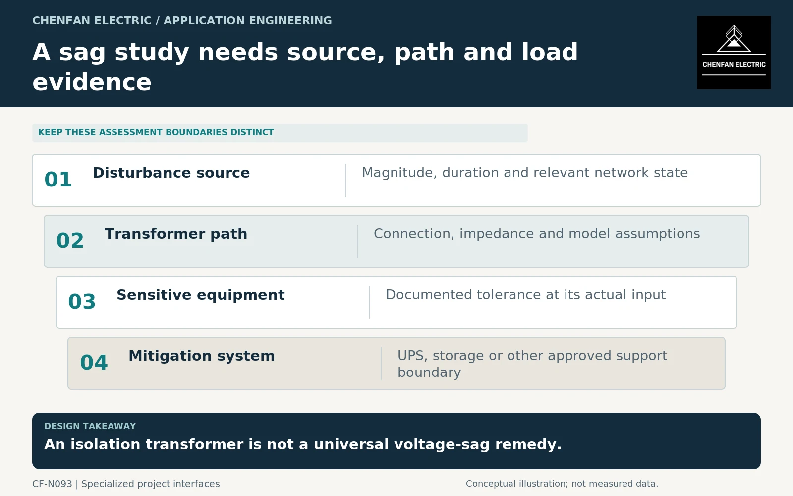
Define the disturbance and the affected boundary
State where the sag is applied or measured, its magnitude and duration, and the relevant phase conditions. Identify the source configuration and the equipment input at which performance is assessed.
A facility-wide average voltage or a generic transformer impedance cannot describe every sensitive-tool interface. The load’s documented tolerance and the actual electrical path are required.
General transformer application guidance addresses connections and voltage behavior. It does not guarantee process continuity through every upstream disturbance. [1]
Keep measured site events separate from modeled scenarios. A hypothetical sag envelope should not be labeled as a captured waveform or a record from a semiconductor production line.
Supply the transformer parameters the model needs
Provide winding connections, ratios and tap assumptions, impedances on stated bases and the operating configuration. The appropriate model detail depends on the disturbance and the study objective.
Parallel transformers, bus ties and alternate-source states can change the electrical path. Include those configurations where they are permitted, rather than evaluating only the normal single-line diagram.
The transformer cannot create sustained missing energy merely by providing galvanic separation. Any ride-through claim involving stored energy or active conversion must identify the equipment performing that function and its limits.
Uninterruptible power system (UPS) performance requirements address the UPS within their scope. They do not automatically demonstrate the complete transformer-UPS-tool response for the installed facility. [2]
Separate three acceptance questions
| Question | Evidence boundary |
|---|---|
| What disturbance reaches the load? | Network and transformer study or measurement |
| What can the load tolerate? | Equipment-specific performance evidence |
| What does mitigation provide? | Supported operating envelope of the mitigation system |
These conclusions must be reconciled, but none should be substituted for another. A transformer factory test does not demonstrate a process tool’s ride-through, and a tool tolerance curve does not establish the site’s disturbance exposure.
Starting large motors or changing source configurations can create local voltage events that deserve separate cases. Motor-acceleration study tools illustrate the need to represent the source and starting equipment dynamically. [3]
Do not select a universal lower transformer impedance as a cure without considering fault levels, protection and other system consequences. The parameter choice belongs to coordinated design.
Preserve uncertainty and operating restrictions
The enquiry should provide the model-input schedule and request the transformer data needed by the facility study. Identify missing load-tolerance evidence and assumptions about mitigation availability.
Acceptance should distinguish calculated predictions from measured integrated performance. Where a conclusion depends on a particular bus topology or available UPS capacity, retain that restriction in the operating documentation.
Future tool additions and changes to bus-tie operation can alter the assessed boundary without changing transformer MVA. Review those changes against the study rather than assuming a general semiconductor-duty label remains sufficient.
The useful specification gives the system analyst a trustworthy transformer model and a clear equipment boundary. Process continuity then follows from coordinated source, network, load and mitigation evidence—not from an unsupported claim that an isolation transformer eliminates voltage sags.
Core procurement checkpoint: Do not market a core as voltage-sag ride-through equipment
Voltage-sag performance depends on the complete supply system and connected equipment. The core supplier should provide only the agreed geometry, material and manufacturing records for the transformer’s approved design. Those records do not demonstrate that a semiconductor process will ride through a disturbance. Assign model inputs, equipment testing and process-level acceptance to the responsible project parties.
For the core enquiry: Approved transformer/core design; requested manufacturing records; agreed excitation tests if any; owner of sag-study and process acceptance.