

An anisotropic steel model is only meaningful when its material axes follow the actual geometry. Assigning a preferred permeability direction globally can misorient part of a core after limbs, yokes or local sections turn. The material identity and its local coordinate system must be reviewed together.
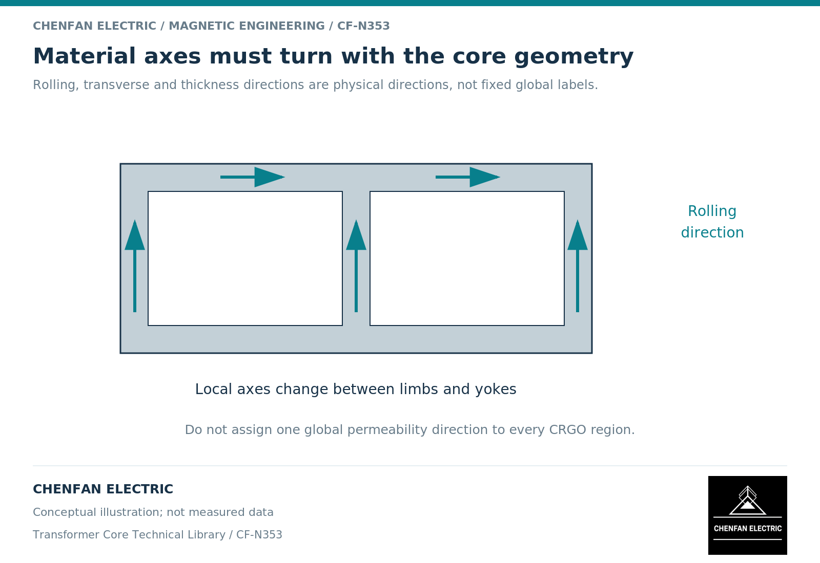
Distinguish geometry axes from material axes
The global x, y and z directions describe the model space. The rolling, transverse and through-thickness directions describe the material. They coincide only where the geometry and material orientation make them coincide.
A directional constitutive relation uses that mapping to determine how magnetic field and flux density relate. Ferromagnetic modeling guidance distinguishes scalar and tensor descriptions. [1] A tensor entered correctly but rotated incorrectly still describes the wrong material response in the assembly.
The same issue applies to a nonlinear directional model. Naming a region “grain-oriented steel” does not prove that the solver has been given the intended direction-dependent data or orientation.
Review the axis map before reviewing contours
Display local axis arrows on the geometry without field contours. This makes orientation errors easier to see. Check representative limbs, yokes, corners, return sections and any separately rotated component.
For a laminated assembly, distinguish in-plane preferred direction from the stacking direction. They control different aspects of the effective material response. A model can represent lamination direction while still using an oversimplified in-plane relation.
The finite-element manual describes directional permeabilities and bulk lamination orientation as separate material inputs. [2] That separation should be preserved in the engineering review rather than collapsed into one generic anisotropy setting.
Use controlled rotation checks
A simple verification model can compare a uniform specimen aligned with the preferred direction and the same specimen rotated relative to the applied field. The result should follow the supplied directional data and the chosen constitutive model.
This is a numerical consistency check, not a replacement for measured off-axis data. Rotating a longitudinal curve does not create the missing transverse or rotating-field characteristic.
For an assembled core, inspect regions where the field departs from the preferred direction. The purpose is not to claim that all such regions are defective; it is to ensure that the model used to evaluate them has an appropriate material boundary.
Keep the data limitation attached to the result
| Review item | Required evidence |
|---|---|
| Material basis | Identified grade, condition and dataset |
| Local axes | Mapping to rolling and stacking directions |
| Directional response | Data or justified model for relevant field directions |
| Coordinate transformations | Consistent assignment after geometry changes |
| Validation | Comparison relevant to the intended directional behavior |
A local-loss claim requires more than a directional permeability assignment. The loss model must also support the field trajectory and direction. A scalar loss curve evaluated at the magnitude of a rotating field may not reproduce the actual dissipative behavior.
The handover should include an orientation map with the geometry revision. If a packet, yoke region or model component is rotated during a design change, its material coordinates must be checked as part of that change.
For the core manufacturer, this provides a clear relationship between the evaluated material direction and the released component definition. It avoids a situation in which a precise manufacturing layout is assessed by a simulation that unintentionally treats every region as pointing in the same direction.
References
[1] Cesare Tozzo / COMSOL. Modeling Ferromagnetic Materials in COMSOL Multiphysics.
[2] David Meeker. Finite Element Method Magnetics User Manual.