

A magnetic-thermal model must transfer the location of heat generation, not just the total core loss. It must also represent the paths by which heat leaves the assembly. Multiplying a uniform watts-per-kilogram value by the core mass may estimate a total under restricted assumptions; it does not provide a measured local heat-source distribution or a hot-spot prediction.
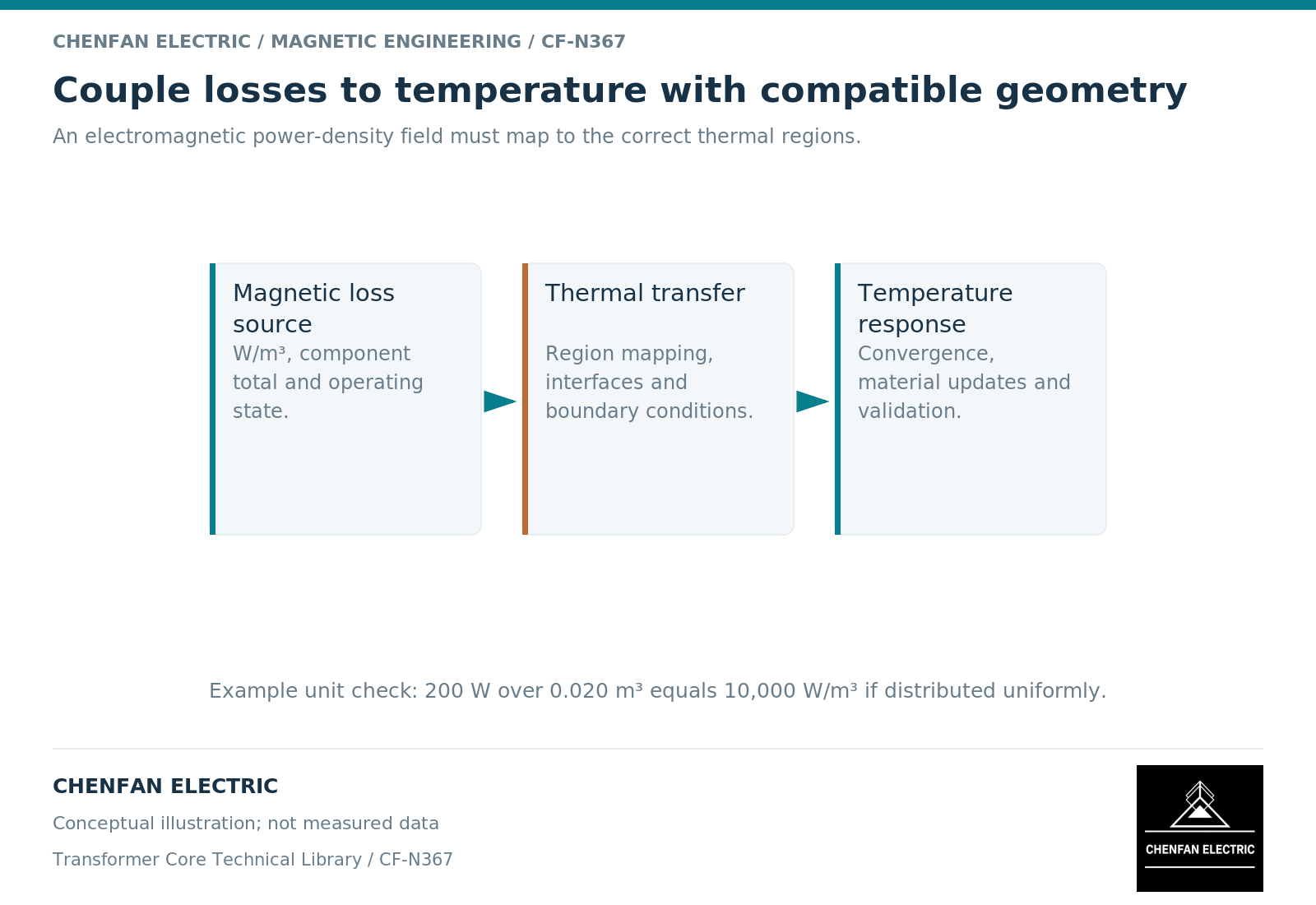
Keep the transferred quantity physically consistent
Electromagnetic analysis may produce volumetric loss density in W/m³, surface loss in W/m², or integrated power in watts. Thermal analysis needs a compatible source on the corresponding domain or boundary. Converting between these forms requires the represented volume or area.
For an illustrative uniform region of 0.020 m³ receiving 200 W, the equivalent volumetric source is 10,000 W/m³. That arithmetic preserves total power, but uniformity is an assumption. If the actual 200 W is concentrated near a joint or clamp, the temperature distribution can be quite different.
Finite-element documentation distinguishes integrated loss quantities, conducting regions and thermal material descriptions. [1] Preserve those definitions when transferring data between models rather than matching numbers by appearance.
Match the loss model to the region
Lamination loss, induced current in solid metal and winding loss do not share one universal constitutive relation. Material direction, excitation waveform and magnetic operating point can matter in the core. Conductivity and field penetration matter in surrounding metal.
Ferromagnetic modeling guidance also distinguishes simple constitutive curves from history-dependent and temperature-dependent behavior. [2] A sophisticated thermal solver cannot compensate for electromagnetic source data outside the material model’s valid range.
State whether the source is cycle averaged or time resolved. A cycle-averaged source can suit a slower thermal response under stable periodic operation. It does not automatically capture a short transient or a changing duty cycle.
Choose one-way or iterative coupling deliberately
In a one-way analysis, electromagnetic losses are calculated at a stated temperature and passed to the thermal model. In an iterative analysis, temperature-dependent properties are updated and the electromagnetic calculation is repeated until the chosen convergence criteria are met.
Iteration is useful only when the updated properties are credible. It should not manufacture precision from an assumed temperature coefficient or an unverified loss curve. A sensitivity range may be more honest than a tightly converged but unsupported prediction.
| Interface | Required consistency check |
|---|---|
| Geometry transfer | Same physical regions and revision |
| Loss transfer | Units, integration and conservation of total power |
| Material update | Applicable temperature and field range |
| Cooling boundary | Flow, contact and ambient assumptions |
| Reported hot spot | Location, averaging and numerical sensitivity |
Verify heat removal as carefully as heat input
Cooling ducts, contact surfaces, surrounding liquid or air, and structural supports influence temperature. Specifying one ambient temperature does not define all these boundaries. The modeled duty duration also matters when thermal equilibrium has not been reached.
A useful validation comparison aligns the measured location and operating condition with the predicted quantity. A bulk liquid temperature is not a direct measurement of an internal core hot spot; a surface sensor is not a volume average.
The release record should retain the source map, total-power check, thermal boundaries, property dependencies and residual uncertainties. This makes a coupled model useful for decisions while preventing its temperature contours from being presented as factory measurements or guaranteed operating temperatures without the necessary evidence.
References
[1] David Meeker. Finite Element Method Magnetics User Manual.
[2] Cesare Tozzo / COMSOL. Modeling Ferromagnetic Materials in COMSOL Multiphysics.