

A closed conducting path linked by changing magnetic flux can carry an induced current even when it is not part of a power winding. Clamping hardware deserves attention because several ordinary components can combine into such a path. The important question is the complete loop and its linked flux, not whether one individual bolt appears harmless.
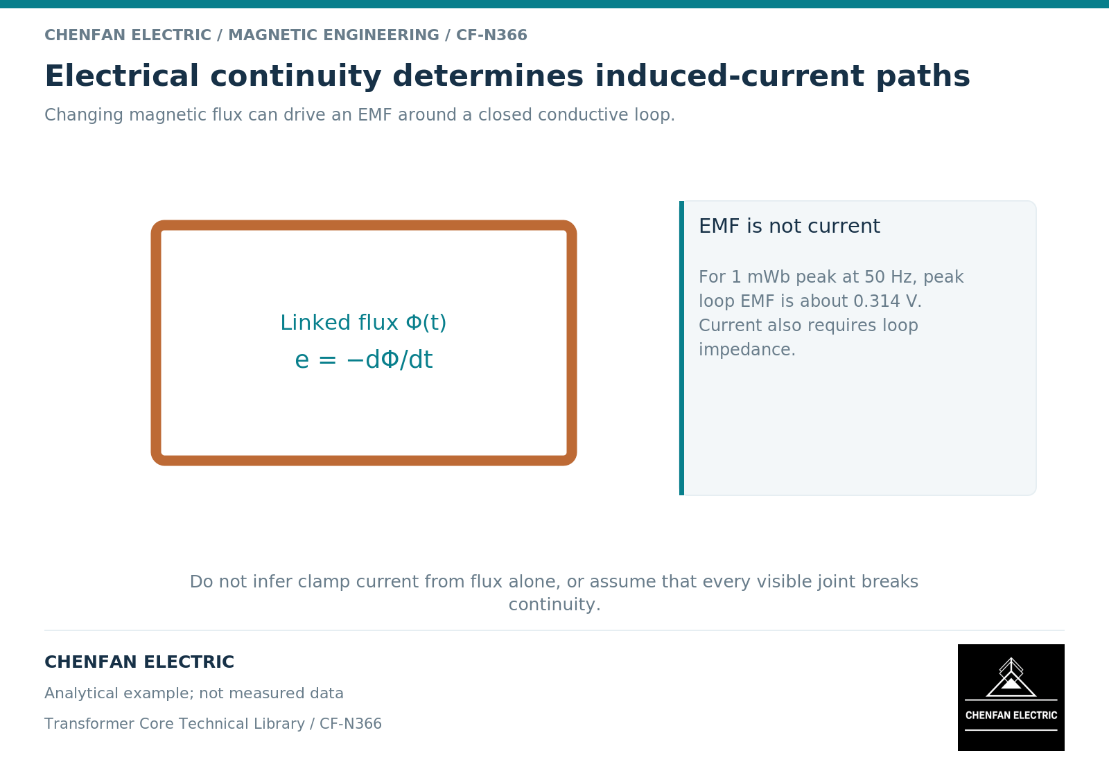
Follow the loop across component boundaries
Faraday’s law relates induced electromotive force around a closed path to the rate of change of linked magnetic flux. [1] A path may include a clamp, fasteners, supports and another structural member. Its electrical impedance, not only its resistance, affects the resulting current under alternating excitation.
A useful conceptual sketch has two separate layers: the magnetic flux crossing the loop area and the connected conducting route around that area. A mechanical assembly drawing often shows the second incompletely because electrical continuity was not its original purpose.
Loop area alone is not enough. Orientation, field nonuniformity and phase cancellation affect the linked flux. A large loop in a weak or canceling field may behave differently from a smaller loop in an intense winding-end region.
Avoid the ideal shorted-turn shortcut
Calling every suspected hardware loop a “shorted turn” can suggest a level of coupling that has not been demonstrated. A loop around a limb, a loop near a winding end and a localized eddy-current path inside one plate may link very different fluxes.
Field formulations account for conductivity and induced-current distribution within represented metal regions. [2] They also show why replacing a distributed structure with one lumped loop needs justification. The simplification must preserve the relevant linkage and impedance.
An illustrative loop with 0.001 Wb sinusoidal peak linked flux at 50 Hz has a peak induced electromotive force of 2π × 50 × 0.001, approximately 0.314 V. This does not establish its current: the loop impedance and actual flux response are still required. Nor does it establish a temperature without a thermal model.
Keep hardware circulation distinct from core grounding
The intentional core-ground connection controls the electrical potential of the designated core assembly. An unintended structural loop is an electromagnetic and assembly question. The two can interact, but eliminating one in a drawing is not permission to remove protective or functional grounding.
A diagnosis should identify the nodes and physical interfaces involved. A high reading on a designated ground lead does not prove that every clamp connection is at fault; a hardware hot spot does not alone establish multiple core grounds.
Review evidence before authorizing changes
| Evidence | What it can establish |
|---|---|
| Controlled connection drawing | Intended conducting and insulating interfaces |
| Verified assembly observation | Whether a particular connection exists |
| Field and circuit analysis | Expected linkage and current distribution |
| Thermal evidence | Heating under identified operating conditions |
| Approved modification record | The authorized final configuration |
This sequence is a review framework, not a work procedure. It deliberately provides no instructions for disconnecting, insulating or cutting installed hardware.
The manufacturing handover should preserve any electrically significant interface as clearly as its mechanical dimensions. The designer then retains responsibility for deciding which conductive paths are intentional and which require prevention. That is more reliable than treating a clamp as a collection of unrelated metal parts and discovering the electrical network only after assembly.
References
[1] Lloyd Dixon / Texas Instruments. Magnetics Design 1 – Introduction and Basic Magnetics.
[2] David Meeker. Finite Element Method Magnetics User Manual.