

A port electrification plan should distinguish crane drives, shore-to-ship power and vehicle charging before combining their transformer requirements. These loads can differ in frequency interfaces, regeneration, demand timing and continuity needs. A single port-wide megawatt total is useful for planning, but it cannot define every transformer or justify sharing infrastructure without a coordinated operating matrix.
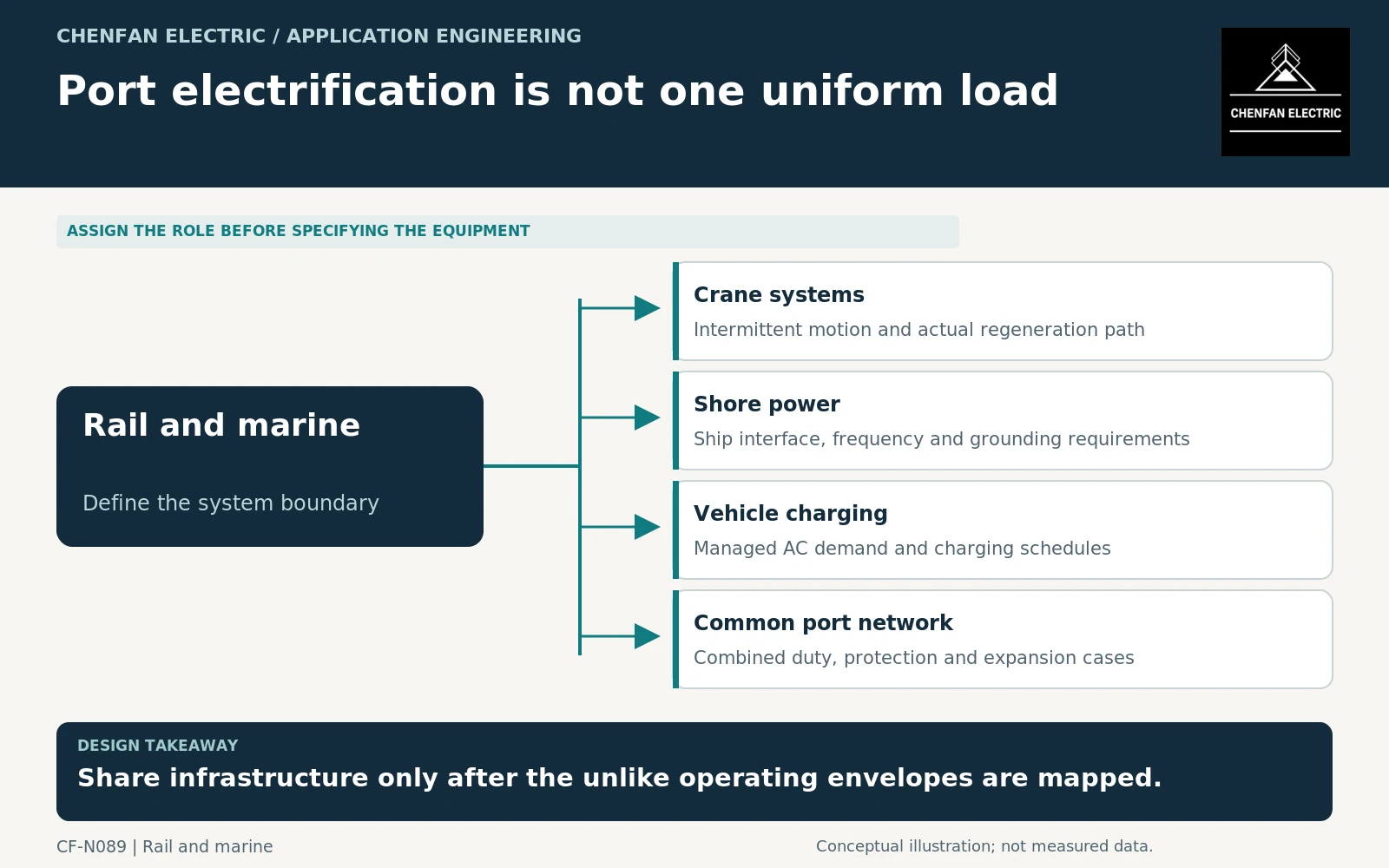
Map the three principal load interfaces
Crane drives may import, regenerate or exchange energy within their conversion system depending on the selected architecture. Shore power may require voltage transformation, frequency conversion and coordinated ship-network interfaces. Charging equipment has its own alternating current (AC) input and session schedule.
Converter-transformer application guidance is relevant where specialized conversion equipment defines the transformer duty. It does not make these three applications electrically interchangeable. [1]
The high-voltage shore-connection framework and direct current (DC) charging-equipment framework have different scopes. Neither should be applied indiscriminately to the port’s entire distribution system. [2] [3]
Identify what can share a transformer
A common transformer may supply several services when voltage, current, waveform, grounding and operating requirements are compatible. Separate transformers may resolve frequency-conversion, protection or availability boundaries. The choice should follow the architecture rather than an assumed preference for fewer units.
A net active-power total can conceal individual branch duty. A crane returning energy while chargers consume power may reduce upstream net import, but the local branches still carry their own currents. Reactive power and harmonics also remain relevant.
General transformer application guidance supports reviewing connections and ratings. The project must supply the actual simultaneous states and network model. [4]
Do not assume that favorable cancellation persists. Vessel schedules, crane operations and charging queues can change independently, so an average port energy profile may not represent the governing equipment case.
Compare operating and unavailable-service states
| Port state | Interface question |
|---|---|
| Vessel connected with cranes active | Which frequency and demand boundaries remain separate? |
| Peak vehicle charging | What managed AC limit is enforced? |
| Crane regeneration | Where can returned energy flow? |
| Shore-converter unavailable | Which other port services are affected? |
| Network maintenance | What common equipment must be isolated? |
The port’s operating plan should identify acceptable service reductions and essential functions. A shared transformer creates a common outage boundary that may be acceptable for some services and unacceptable for others.
Future expansion should be defined by service type as well as total power. Adding another shore connection can create a different interface requirement from adding the same nominal power in managed vehicle chargers.
Issue coordinated but distinct equipment schedules
Each transformer enquiry should receive its own terminal duty, voltage and frequency conditions, converter data, environmental exposure and availability cases. Cross-reference shared network assumptions so suppliers do not design against conflicting boundaries.
Acceptance should separate equipment tests from integrated service demonstrations. A transformer factory report does not validate ship compatibility, crane regenerative controls or charger demand management.
The practical output is a port electrical architecture that explains which services share equipment, which remain separate and why. “Port electrification transformer” is too broad to establish those choices. The load interfaces—not the common geographical location—determine the technical specification.
Core procurement checkpoint: Use separate core design IDs across port services
Port cranes, vehicle chargers and shore connections can require different transformer designs. Do not group them under one core specification simply because they share a project or utility connection. Use an approved core schedule by equipment function, with material, geometry and quantity controlled for each variant. System compatibility and marine or charging qualification remain with the respective equipment and project teams.
For the core enquiry: Equipment-function schedule; core drawing per variant; material specification; quantity; set labeling and inspection scope.