

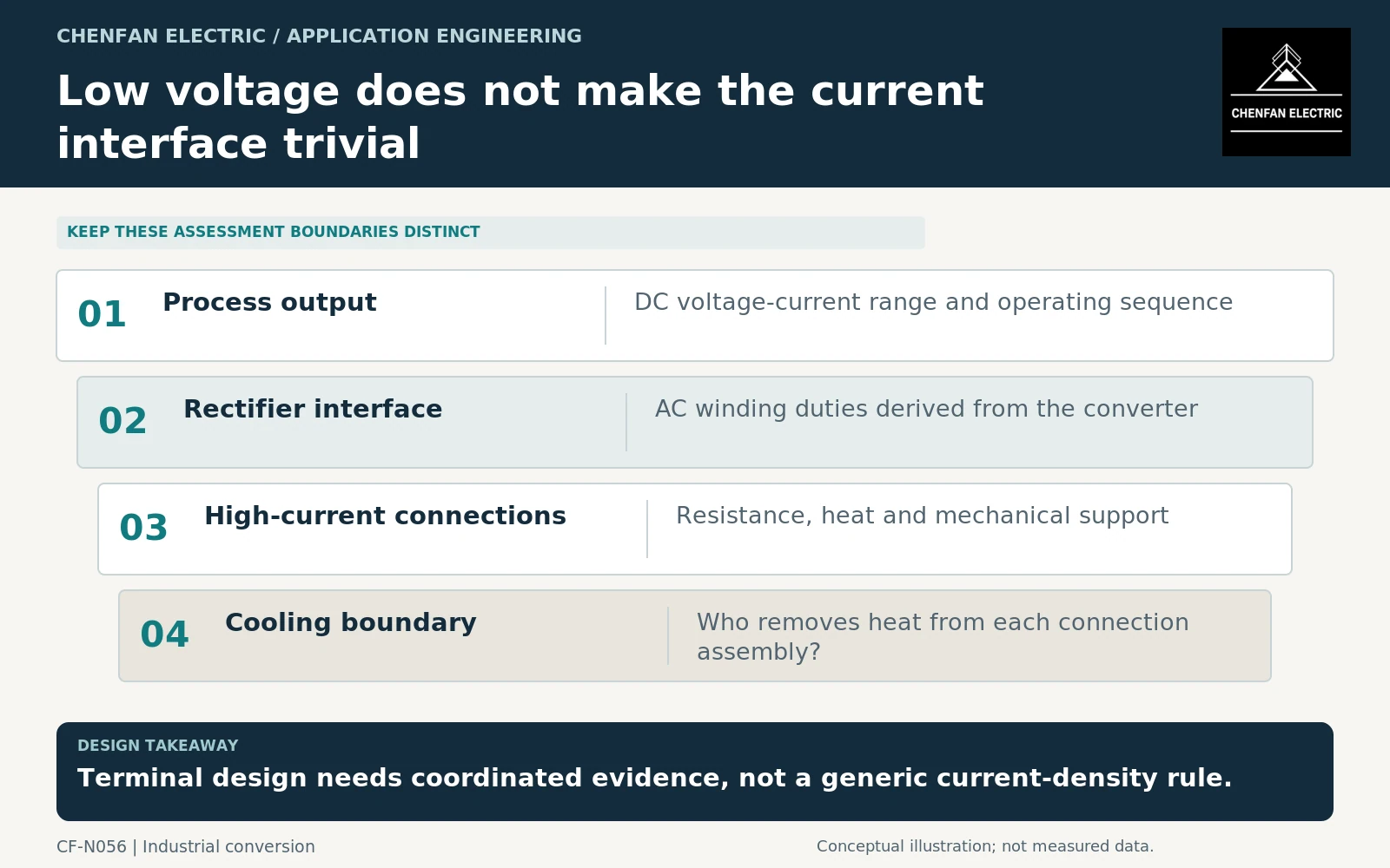
An electroplating rectifier-transformer enquiry should treat the low-voltage, high-current connection as a major design interface. A modest voltage does not make terminal heating, contact resistance or mechanical support unimportant. Define the process direct current (DC) range, obtain the rectifier’s alternating current (AC) winding requirements and coordinate the busbar, cooling and terminal boundaries before comparing transformer offers.
Translate the process requirement through the rectifier
The plating process supplies the required DC voltage-current range and duty sequence. The rectifier supplier then defines the AC winding arrangement, currents, regulation and waveform imposed on the transformer. These are related quantities, not interchangeable ratings.
IEC 61378-1 addresses industrial converter transformers within its scope, and its application guide covers associated system considerations. [1] [2] A standard distribution-transformer description cannot replace the converter-specific interface schedule.
State whether the process operates continuously, cycles between stages or requires temporary current changes. Include simultaneous operation where several process lines share equipment. An average production power can conceal a governing high-current interval.
Make connection resistance visible in the heat balance
At high current, small resistance can produce significant heat. As an illustrative arithmetic example, 10 kA through an assumed 10 micro-ohm connection produces I²R = 1 kW. This is not an acceptable-resistance limit or a busbar design rule; it shows why connection evidence matters.
The relevant resistance and temperature behavior depend on the actual joint, materials, contact condition and current path. Do not select terminal hardware from a generic current-density number without the responsible electrical and thermal design.
Identify which party supplies each mating surface, connection plate, flexible section and support. A transformer terminal guarantee should not silently include an unspecified customer busbar, and a busbar supplier should not assume unlimited terminal mechanical loads.
Coordinate the complete high-current assembly
| Interface | Information to agree |
|---|---|
| Electrical | Current waveform, magnitude and permitted operating range |
| Thermal | Heat sources, cooling method and boundary temperatures |
| Mechanical | Connection geometry and allowable equipment-interface loads |
| Maintenance | Inspection, access and approved replacement boundaries |
| Acceptance | Which assembly and conditions the evidence represents |
The cited fittings standard concerns liquid-immersed power-transformer and reactor accessories, but they do not qualify every project-specific high-current connection. [3] The complete arrangement needs a coordinated acceptance basis.
Where cooling is shared with the rectifier or process system, specify the actual medium and supplied conditions. “Water cooled” is insufficient without identifying which circuit contacts which component and who owns leakage or loss-of-flow response.
Keep transformer and rectifier guarantees separate
The transformer supplier should confirm its winding duties and specified equipment characteristics. The rectifier supplier should confirm DC output performance and regulation under the agreed AC supply conditions. The integrator should close the shared physical and cooling interfaces.
IEEE C57.110 is not a blanket design basis for these rectifier transformers because its scope excludes that equipment class. [4] Use the applicable specialized framework and project evidence instead of a generic harmonic label.
The purchasing package is complete when current, voltage, connection geometry, cooling and responsibility are consistent across the process, rectifier and transformer documents. Low output voltage does not reduce the need for that coordination; high current often makes the boundary between suppliers more consequential.
Core procurement checkpoint: Keep high-current connection design outside the core boundary
The low-voltage, high-current interface is a responsibility of the complete rectifier-transformer design. For a core order, freeze the winding envelope and required assembly access without claiming that the supplied steel qualifies terminals, busbars or cooling. A quotation should clearly distinguish core material and processing from the manufacturer’s connection-loss, mechanical-force and thermal assessments.
For the core enquiry: Approved core and coil-envelope drawing; assembly clearances; grade/thickness; delivery form; excluded busbar and terminal responsibilities.