

An electrolyzer rectifier transformer should be specified from the selected converter topology and its alternating current (AC) winding duties. Electrolyzer direct current (DC) megawatts alone do not define the required winding voltages, phase shifts, currents or regulation range. Establish the conversion architecture first, then translate the electrolyzer operating envelope into the quantities imposed on each transformer winding.
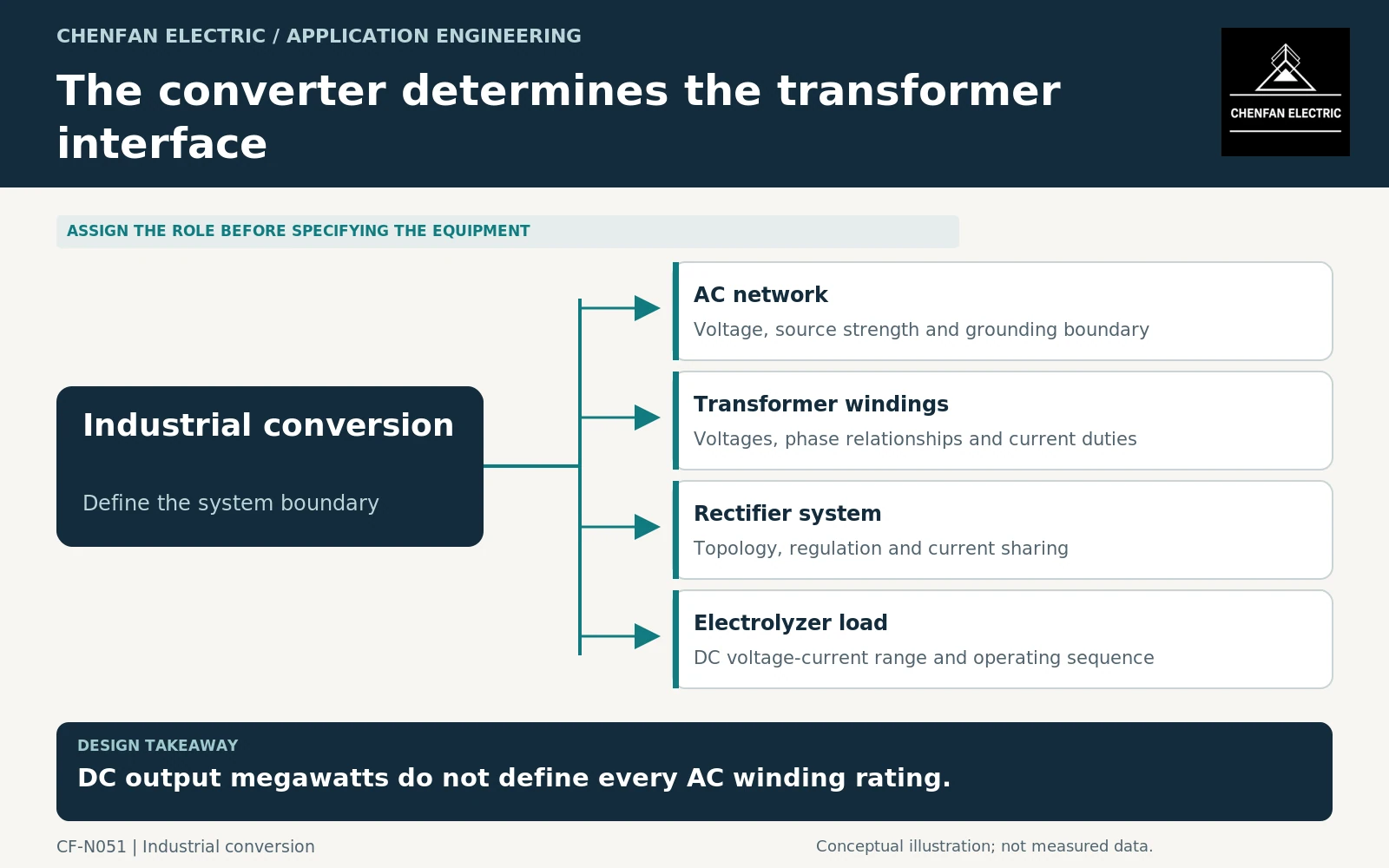
Start at the DC load, but do not stop there
Obtain the electrolyzer’s DC voltage-current operating range, minimum operating state, startup requirements and permitted power changes. Identify whether those values apply to one stack, a group of stacks or the complete plant.
The rectifier supplier must translate that requirement into an AC interface for its chosen topology. Conversion losses, waveform, control method and current sharing intervene between DC output and transformer input. A simple division of DC power by nominal AC voltage cannot establish a complete winding schedule.
IEC 61378-1 addresses industrial converter transformers within its defined scope, including issues associated with semiconductor conversion and winding arrangements. Its application guide provides further context for selecting and coordinating such equipment. [1] [2]
Freeze the topology before quoting the transformer
Identify the converter arrangement, number of electrical groups, required phase relationships and any regulating transformer or tap-changing function. Different converter approaches can produce different transformer requirements for the same electrolyzer DC output.
Ask which party owns the transformation from stack data to winding data. The transformer supplier should not be expected to guess the rectifier topology, and the converter supplier should not assume an unspecified transformer can provide any desired secondary arrangement.
The interface package should include winding voltages and currents, simultaneous operating conditions, phase displacement, impedance requirements on stated bases, grounding arrangements and converter-specific waveform data. Where multiple bridges share load, record the current-sharing assumptions and relevant tolerances.
Separate regulation from available capacity
An electrolyzer may require an operating voltage range that changes with process conditions. The converter and transformer arrangement must define how that range is achieved and what current or power restrictions accompany it.
A tap range is not automatically a continuous online regulating capability. State which device changes the ratio, when it may operate and how it coordinates with converter controls. Do not assume that every tap position supports every advertised output combination.
For a hypothetical 10 MW DC operating point at 1,000 V, DC current is 10 kA. That calculation describes the DC load only. It does not specify a 10 kA AC winding, a transformer MVA rating or a busbar design. The converter topology determines the relationship between those quantities.
Request evidence at each boundary
| Boundary | Evidence required |
|---|---|
| Electrolyzer to converter | DC operating envelope and process sequence |
| Converter to transformer | Winding schedule, waveforms and regulation assumptions |
| Transformer to network | Input duty, impedance and relevant system-study model |
| Physical assembly | Terminal, cooling and access interfaces |
| Integrated system | Agreed operating cases and acceptance responsibilities |
IEEE C57.110 should not be used as a blanket substitute for this specialized specification: its published scope excludes rectifier transformers. [3] The applicable converter-transformer framework and project evidence must be selected deliberately.
Keep the procurement claim specific
Require offers to identify the exact winding arrangement and operating cases covered. A generic “hydrogen transformer” description is not enough, and an educational discussion of electrolyzer supply does not establish a supplier’s manufacturing capability or project qualification.
The completed specification should let the electrolyzer, rectifier and transformer teams trace the same operating envelope across their interfaces. That is the point at which a meaningful technical and commercial comparison becomes possible. Quoting the transformer before those boundaries are defined risks pricing different electrical systems under the same DC megawatt label.
Core procurement checkpoint: Require a converter-specific core drawing
Electrolyzer DC power and current do not define the core’s geometry or the AC winding arrangement. The transformer designer should approve the magnetic design for the selected rectifier topology before laminations are released. A drawing-based core supply review should identify manufacturing feasibility and agreed inspection records without implying that the core supplier has designed or qualified the complete electrolyzer rectifier package.
For the core enquiry: Rectifier topology reference; approved core and winding-envelope drawing; grade/thickness; joint sequence; quantity and inspection boundary.