

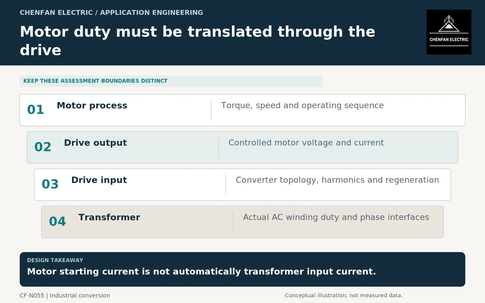
A transformer supplying a variable-speed drive should be specified from the drive’s input characteristics, not only the motor’s nameplate power. The converter topology determines input current, harmonic behavior, phase-group requirements and whether regeneration can return energy upstream. Motor output duty remains important, but it must be translated through the selected drive before it becomes transformer duty.
Identify the drive front end
Record whether the drive uses a simple rectifier arrangement, multiple phase groups, an active front end or another specified topology. Include filters and any transformer functions integrated into the drive package.
The same motor power can be served by drives with different input waveforms and transformer arrangements. A generic “variable-frequency drive (VFD) transformer” description therefore leaves too much unresolved for a meaningful quotation.
Industrial converter-transformer requirements and application guidance provide a framework for these interfaces within their scopes. [1] [2] The drive supplier must still provide the actual winding schedule and operating envelope for the purchased configuration.
Translate the motor process into input duty
Obtain the motor torque-speed sequence, acceleration requirements and expected operating duration, then ask the drive supplier for the corresponding input demand. Do not assign direct-on-line motor starting current to a drive-fed transformer without analyzing the actual conversion system.
A drive can limit or shape the motor-side start, but that does not mean every acceleration is electrically insignificant upstream. The available source, drive controls, process inertia and permitted acceleration time must be considered together.
Motor-starting and drive-analysis tools recognize that starting devices and dynamic models change the study. Their documentation is evidence of the required analysis distinction, not proof that a particular drive-transformer combination has been validated. [3]
Include regeneration and low-speed operation correctly
A regenerative motor event does not necessarily mean energy reaches the upstream transformer. Some systems return energy through an active front end; others dissipate it or exchange it within a direct current (DC) link. Identify the actual path before specifying reverse-power duty.
Likewise, low motor speed does not directly determine transformer input frequency. The upstream transformer commonly remains connected to the supply frequency while the drive controls motor output. Frequency and waveform must be stated at the transformer terminals.
| Drive information | Transformer relevance |
|---|---|
| Front-end topology | Input waveform and phase-group arrangement |
| Input capability | Continuous and temporary current envelope |
| Acceleration profile | Duration and repeated duty |
| Regeneration path | Whether upstream reverse power occurs |
| Filter configuration | Validity of harmonic data |
| Source assumptions | Voltage and impedance compatibility |
Specify evidence and change control
Ask for mode-specific current spectra and distinguish typical data from guarantees. Harmonic heating and network voltage distortion are related but separate assessments. A low distortion figure at one load point does not establish every operating condition. [4]
The transformer offer should reference the drive model, topology and data revision. It should identify any limitation on winding asymmetry, temporary current or cooling availability. Physical terminal and service interfaces should be coordinated with the drive package rather than left to site improvisation.
The acceptance boundary must also be clear: transformer tests establish specified equipment characteristics, while integrated drive performance requires system-level evidence. Changing the drive front end or enabling regeneration can trigger reassessment even when the motor nameplate remains unchanged.
The useful purchasing rule is straightforward: specify the drive that the transformer supplies, and use the motor process to define that drive’s duty. Do not skip the converter between them.
Core procurement checkpoint: Carry the drive-transformer variant into the lamination schedule
A drive transformer may have a particular winding arrangement and mechanical envelope that are not captured by motor kilowatts. Give the core supplier the approved design for the selected drive topology, including packet sequence and assembly interfaces. A shared steel grade does not make different drive-transformer cores interchangeable, and a lamination certificate does not establish the drive system’s harmonic performance.
For the core enquiry: Drive topology reference; approved core geometry; window/limb interface; joint sequence; material and inspection specification.