

Motor-start voltage dip cannot be judged from transformer kVA alone. The result depends on source strength, transformer positive-sequence impedance, feeder impedance, motor locked-rotor current or starting-current profile, starting power factor, acceleration time and any other motors or converters already connected. A static calculation can screen the worst instant, but a dynamic study is needed when motor speed, torque, contactor ride-through or generator controls materially change during acceleration.
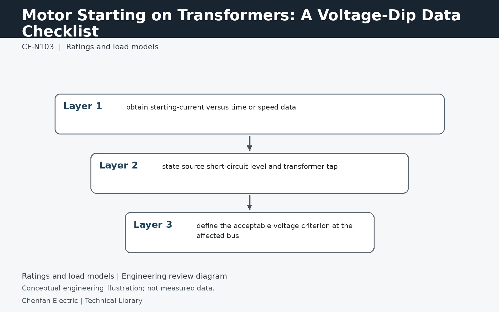
Model the voltage at the motor terminals
The transformer secondary bus is not necessarily the limiting voltage location. Include the cable between that bus and the motor, and identify other equipment exposed to the same dip. Use the starting method actually ordered: direct-on-line, soft starter and variable-frequency drive inputs are not equivalent. For a soft starter, a current limit does not by itself describe available accelerating torque. For a drive, request the supply-side current profile and ride-through requirements rather than copying the motor's locked-rotor current into the supply model.
Use a simple impedance screen with clear limits
For illustration, take starting current equal to three times the transformer rated current and a transformer impedance magnitude of 6%. The product 3 × 0.06 = 0.18 per unit indicates a potentially significant transformer impedance drop. It is not a validated 18% terminal dip: current angle, source impedance, voltage-dependent starting current and feeder drop still matter. If the screen is close to an equipment ride-through limit, use a network calculation rather than treating the product as an acceptance result.
Check the duration as well as the deepest dip
For an induction motor at a fixed frequency, starting torque is approximately proportional to voltage squared over the relevant operating region. A lower voltage can therefore extend acceleration and keep the system depressed for longer. Retain the driven-load torque curve, inertia, permissible starts and hot/cold starting duty. Compare the calculated voltage-time trajectory with motor acceleration, contactor dropout and converter ride-through requirements separately. A solution that reduces the initial dip but prevents acceleration has not solved the starting problem.
Technical reference framework
[1] IEC 60076-1:2011 — Power transformers, General.
[2] IEC 60076-8:1997 — Application guide.