

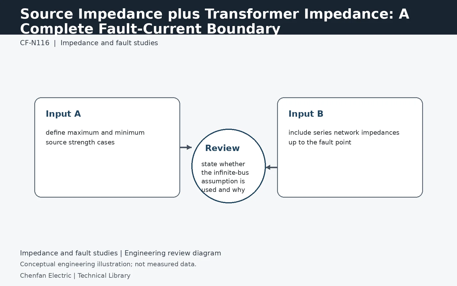
Transformer impedance alone defines only one part of the fault-current boundary. Upstream source impedance, lines, cables, reactors and generator subtransient behavior can materially reduce or reshape the current seen at the transformer secondary. For maximum and minimum fault studies, use the applicable source cases and network topology rather than assuming an infinite bus unless that assumption is deliberately conservative and documented.
Translate source fault level into study impedance
When a source is represented by a three-phase short-circuit level, a simplified per-unit source impedance magnitude is Sbase/Ssc on consistent voltage bases. A 250 MVA source on a 10 MVA study base therefore gives 0.04 per unit. With an 8% transformer, an illustrative predominantly reactive series model totals 0.12 per unit and produces about 8.33 per unit terminal current, rather than the 12.5 per unit inferred from the transformer alone. Full calculations retain the complex impedances and the applicable voltage factors.
Maximum current and minimum sensitivity use different cases
Maximum duty may involve the strongest utility source, low impedance within its permitted band and all credible infeeds. Minimum fault current may occur with one source removed, a long feeder, higher conductor temperature or generator supply. The latter can govern whether protection operates promptly. A single “available fault current” number cannot represent both purposes. Ask the utility for the required maximum/minimum source cases and their X/R basis, and record the network operating state used to combine them with transformer data.
Draw the complete path to the fault location
Include cables, bus ducts, reactors and the actual parallel paths to the fault. Contributions from rotating machines and other sources should follow the chosen study method; they are not removed merely by using an infinite upstream bus. State whether the fault is at the transformer terminals or farther downstream. Save source data dates and planned network changes with the result. A transformer replacement review using an old utility fault level can understate duty even when the new transformer impedance has been entered correctly.
Technical reference framework
[1] IEC 60076-1:2011 — Power transformers, General.
[2] IEC 60076-5:2006 — Ability to withstand short circuit.
[3] IEC 60076-8:1997 — Application guide.