

A three-winding transformer has three pairwise short-circuit impedances: between each pair of windings with the third winding in the specified test condition. These are not three independent series impedances that can be inserted blindly into a network. Study software may convert the pairwise values into an equivalent star of leakage impedances, and consistency should be checked before use.
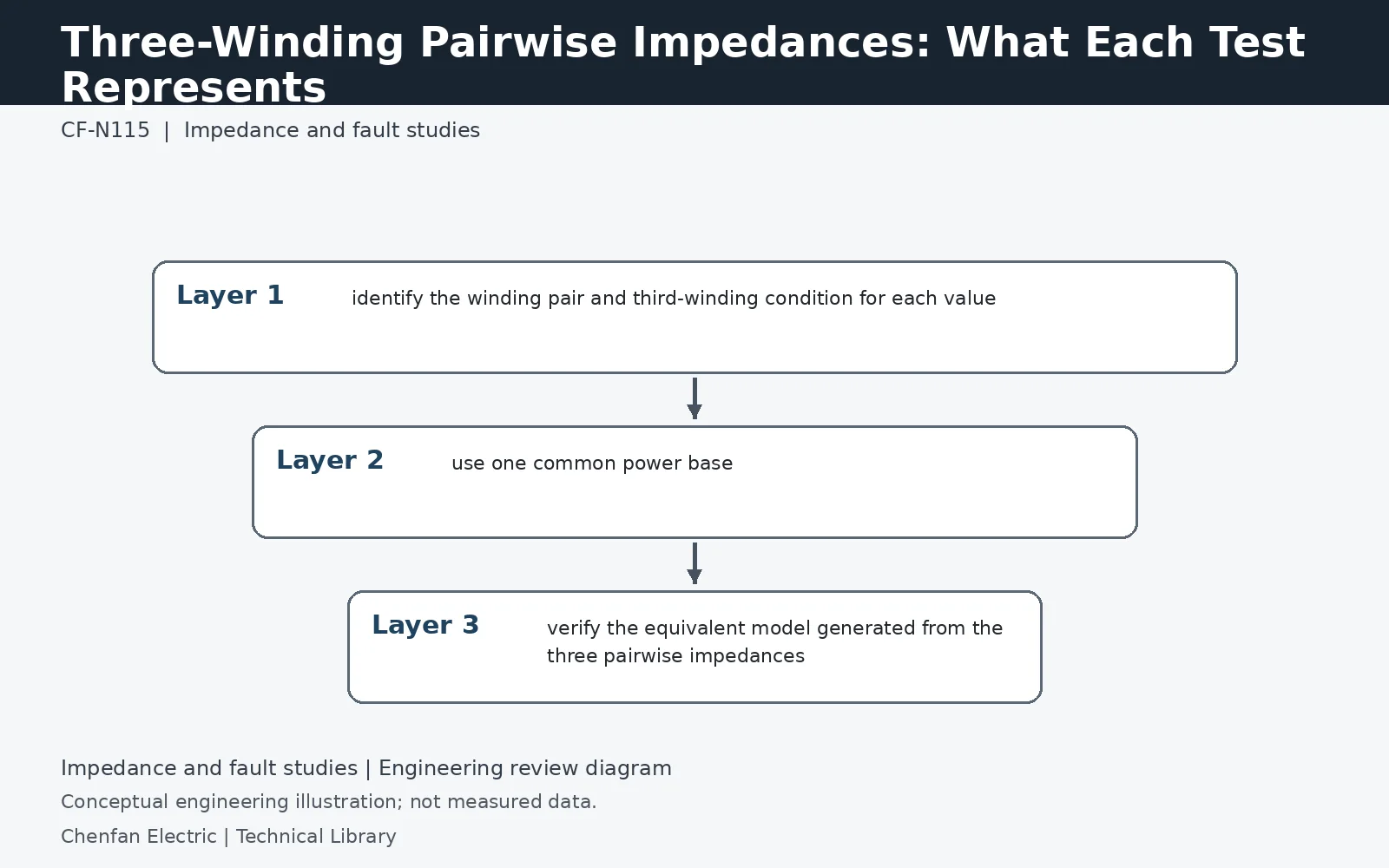
Identify what was energized, shorted and left open
A typical pairwise short-circuit test energizes one winding, shorts the paired winding and leaves the remaining winding open, with the detailed arrangement defined by the test procedure. Record the actual arrangement instead of assuming that every reported impedance uses identical conditions. The tested winding ratings may differ, so the manufacturer's percentage values may not share one MVA base. Request the three pairs together with test tap, frequency and temperature reference before importing them into software.
Convert the pair values into a star equivalent
On a common base, the simple star-equivalent branches are ZA = (ZAB + ZAC − ZBC)/2, ZB = (ZAB + ZBC − ZAC)/2 and ZC = (ZAC + ZBC − ZAB)/2. For illustrative pure-reactance values of 10%, 8% and 12%, the branches are 3%, 7% and 5%. Recombining any two branches recovers its pair value. Apply the equations to consistent complex impedances where R and X are available; substituting unrelated magnitude percentages can misrepresent the losses and angles.
Do not repair an unusual branch by guessing
Some valid three-winding leakage equivalents can contain a negative branch parameter; it is a mathematical representation, not a literal negative physical reactor. A negative result should prompt a check of bases, winding labels, measurement data and software conventions, not automatic replacement with zero. Confirm the intended model with the manufacturer and analyst. The simple equivalent is useful for power-frequency studies but does not describe the transformer's wideband terminal behavior for steep-front surges or very-fast transients.
Technical reference framework
[1] IEC 60076-1:2011 — Power transformers, General.
[2] IEC 60076-5:2006 — Ability to withstand short circuit.
[3] IEC 60076-8:1997 — Application guide.