

Boundary conditions define the magnetic problem being solved. They are not cosmetic settings added after the geometry is complete. A symmetry plane, external-domain boundary or imposed source can exclude a real return path or force an artificial one if it does not match the operating case.
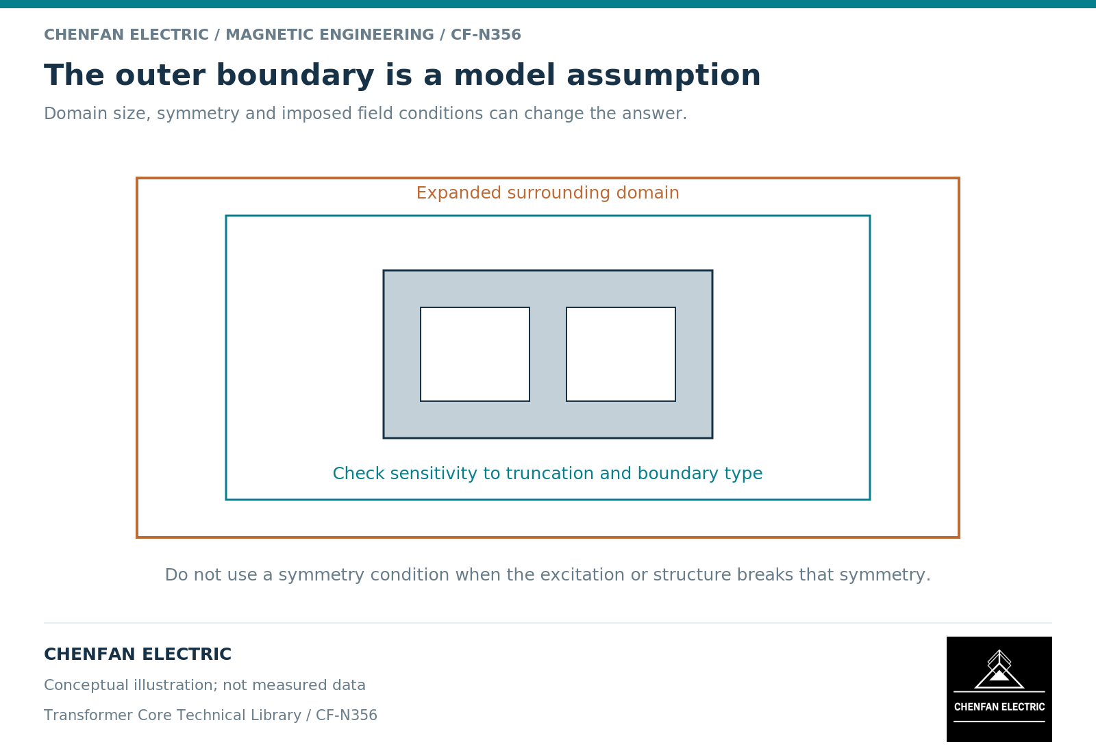
Separate physical boundaries from computational boundaries
A material interface belongs to the physical assembly. The outer edge of a finite analysis domain is often an artificial truncation of surrounding space. Its treatment must approximate the intended open region or other physical constraint.
Finite-element documentation distinguishes prescribed-potential, mixed, periodic and antiperiodic magnetic boundaries. [1] Their names are not interchangeable guarantees of an open or symmetric field.
The chosen condition should be explained in physical terms: which flux behavior or symmetry it imposes, and why that behavior applies to this excitation. A model file containing a default boundary name is not an adequate explanation.
Check whether the excitation preserves symmetry
A geometrically symmetric core can be excited asymmetrically. Single-phase energization, unequal phase voltages, residual states or local structural changes can invalidate a symmetry reduction used for balanced operation.
The same caution applies to periodicity. A repeated geometric feature does not guarantee a repeated field if winding currents or polarities differ. The source pattern and material-axis mapping must satisfy the imposed relationship.
A useful verification is to compare the reduced model with a less constrained model for a representative case. If the reduction changes the relevant result, investigate whether the symmetry assumption or implementation is responsible.
Define current and voltage sources consistently
An imposed current source fixes ampere-turn excitation. A voltage-driven winding allows current to respond to the magnetic and electrical circuit. These are different boundaries, particularly near saturation.
Transformer equivalent-circuit guidance shows that nonlinear branch placement and leakage drops affect the response. [2] A field model coupled to a circuit must use a compatible winding definition rather than combining a fixed current and an independently fixed voltage that overconstrain the same behavior.
Initial magnetic state is another boundary for a transient. It should be physically consistent with the core topology and constitutive model, not selected only to make the solver start easily.
Use a boundary audit before accepting results
| Boundary item | Audit question |
|---|---|
| External region | Does its size or treatment alter the target result? |
| Symmetry plane | Do geometry, excitation and state all preserve the symmetry? |
| Periodic relation | Are phase and polarity relationships correct? |
| Winding source | Is the intended current or voltage duty represented? |
| Material interface | Are continuity and directional properties represented consistently? |
Record the alternatives tested and the resulting sensitivity. A domain-expansion check is especially useful when external return flux or structural fields are important.
Keep the boundary audit linked to the operating-case matrix. A condition justified for one case should not automatically be reused for another case with a different excitation or residual state.
The practical result is a model whose constraints can be explained from the transformer and the question. That is more valuable than a detailed geometry solved under undocumented defaults, and it prevents a numerical boundary from being mistaken for a physical property of the core.
References
[1] David Meeker. Finite Element Method Magnetics User Manual.
[2] Manitoba Hydro International / PSCAD. The Classical Approach.