

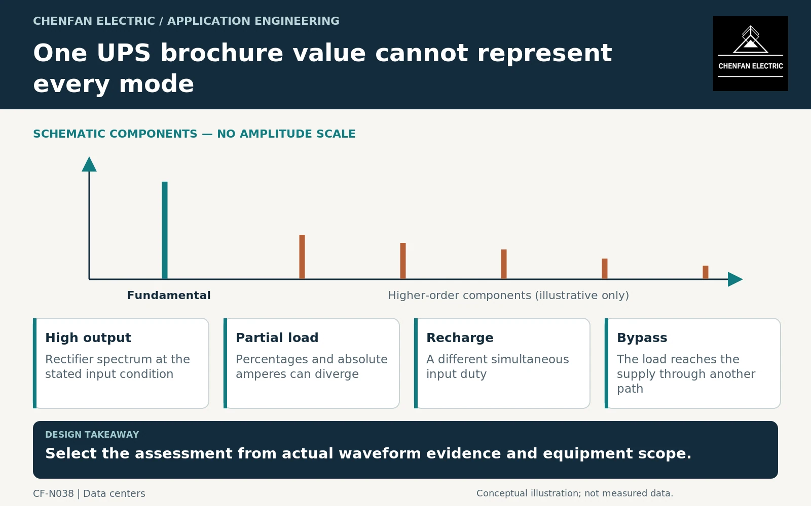
Transformer harmonic requirements for a modern uninterruptible power system (UPS) should follow the installed UPS topology and operating modes, not a blanket assumption that every UPS needs the same K-factor or harmonic allowance. Active front ends, filters, partial-load operation, recharge and bypass can produce different input conditions. The enquiry should obtain the actual evidence before selecting a transformer assessment method.
Establish the UPS configuration being purchased
Identify the rectifier arrangement, optional filtering, number of modules and bypass architecture. Record the source voltage and the operating points associated with harmonic data. A value published for one configuration should not be assigned to another without confirmation.
IEC 62040-3 addresses UPS performance and tests within its scope. It does not provide the complete current spectrum needed for every upstream transformer application. [1]
Ask whether the data are guaranteed limits, typical measurements or simulations. A compliance statement can be relevant evidence, but its measurement boundary and operating conditions must remain visible.
Compare amperes as well as percentages
Current total harmonic distortion is normally referenced to fundamental current. At partial load, the percentage can increase even while absolute harmonic amperes decrease. Conversely, a low percentage at a large fundamental current can still represent a material harmonic duty.
Obtain the relevant spectrum by harmonic order, fundamental current, terminal voltage and duration. Where several UPS modules operate together, identify the aggregation assumption and whether module loading is equal.
ABB’s harmonic guidance explains the system context of nonlinear loads. It supports the need to evaluate actual currents and network effects rather than interpreting one percentage as a complete transformer requirement. [2]
Select the transformer method within its scope
IEEE C57.110 provides a recommended practice for defined power and distribution transformers supplying nonsinusoidal load currents. Its exclusions include rectifier transformers. A dedicated converter transformer should therefore not be assigned that framework indiscriminately merely because it is upstream of a UPS. [3]
Where the arrangement falls within specialized converter-transformer applications, the IEC 61378 framework may be relevant. The equipment definition and converter configuration should determine the specification basis. [4]
| Required evidence | Decision it supports |
|---|---|
| Input spectrum by operating mode | Actual winding-current duty |
| Harmonic-data boundary | Applicability to the transformer terminals |
| Duration and concurrency | Sustained heating assessment |
| Network model | Voltage distortion and equipment interaction |
| Transformer construction and scope | Appropriate assessment framework |
Do not specify a K-factor simply because another facility used it. State what operating evidence and design outcome the requirement is intended to address.
Keep bypass and future changes visible
The bypass path can expose the upstream supply to load characteristics different from those seen through the rectifier. Include maintenance bypass and relevant degraded modes in the data request rather than assuming normal online operation covers them.
Changing UPS modules, enabling different recharge settings or removing an optional filter can alter the input duty. The transformer specification should identify these as review triggers when they affect the approved waveform envelope.
The final enquiry should contain a mode-specific harmonic schedule and a clear statement of the assessment boundary. A supplier can then explain how the proposed transformer addresses the stated duty. That is a defensible technical requirement; a generic “UPS-duty transformer” label without supporting current data is not.
Core procurement checkpoint: Ask for comparable magnetic evidence, not a harmonic label
Modern UPS input-current characteristics should be assessed at the complete-transformer boundary. For core procurement, define the designer’s excitation waveform assumptions and the loss-test basis independently. A low-loss material certificate does not demonstrate harmonic heating performance of windings and structural parts. Any special non-sinusoidal core assessment should be explicitly agreed rather than implied by a general UPS application description.
For the core enquiry: Approved core design; waveform assumptions; grade and thickness; core-test method; scope of any special harmonic assessment.