

The harmonic cancellation associated with a twelve-pulse arrangement assumes the intended relationship between its two six-pulse groups. Unequal currents, impedance differences or phase displacement errors leave residual components. A harmonic spectrum at the common terminal shows the result, but not necessarily its cause. Apply the HVDC transformer specification framework of IEC/IEEE 60076-57-129 to the stated liquid-immersed equipment [1].
Measure or calculate each group before combining them. Refer harmonic phasors through the correct winding ratio and vector connection. Harmonic phase displacement must be derived for that order; applying the fundamental phase shift unchanged to every harmonic is unreliable.
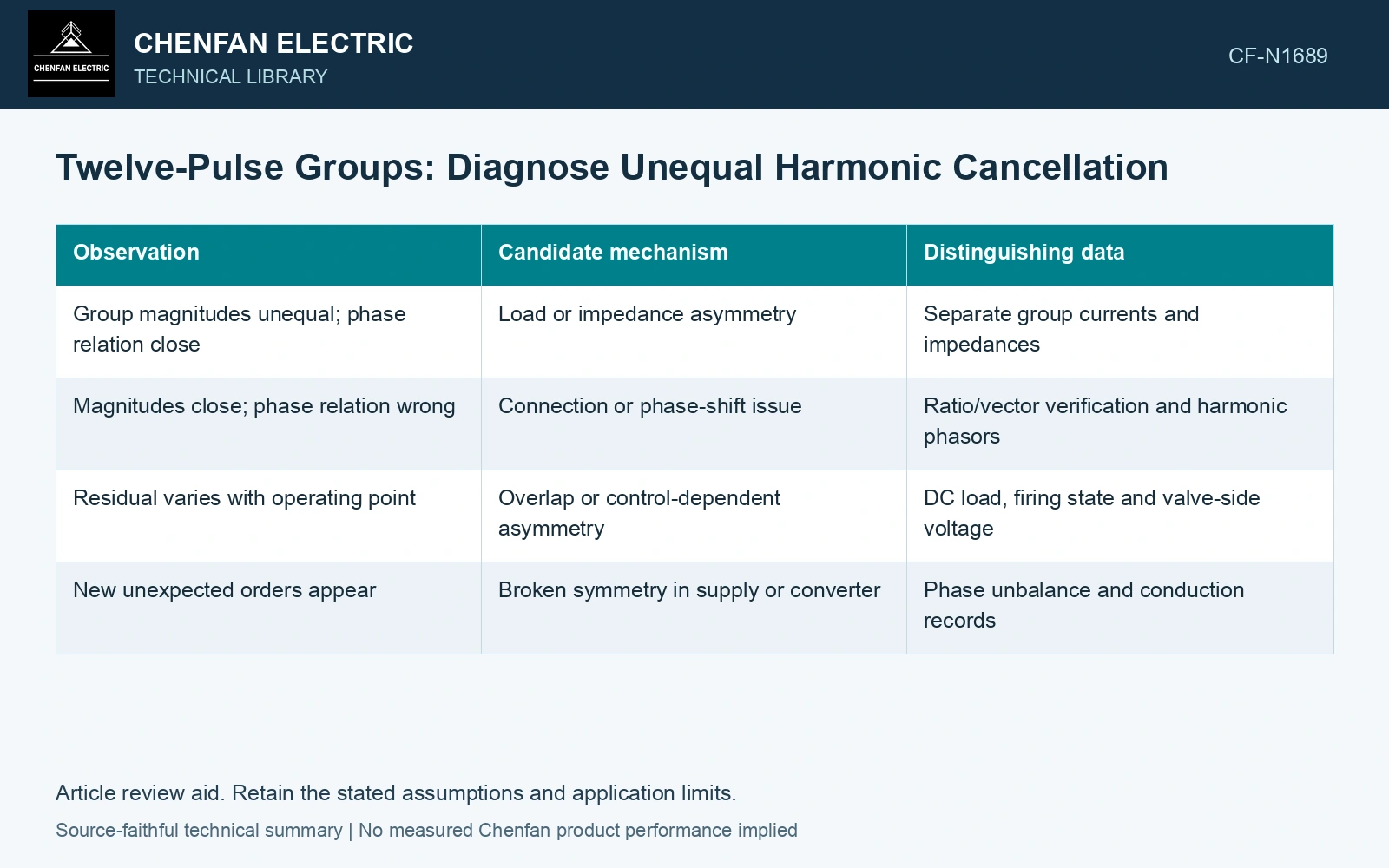
Use phasors to test cancellation
For an order expected to cancel, write two referred contributions as I1 = A and I2 = −B exp(jε). Their residual magnitude satisfies |Ir|² = A² + B² − 2AB cos ε. A and B are harmonic RMS amperes; ε is the residual phase error in radians. Equal magnitude and zero error give zero in this ideal pair.
| Observation | Candidate mechanism | Distinguishing data |
|---|---|---|
| Group magnitudes unequal; phase relation close | Load or impedance asymmetry | Separate group currents and impedances |
| Magnitudes close; phase relation wrong | Connection or phase-shift issue | Ratio/vector verification and harmonic phasors |
| Residual varies with operating point | Overlap or control-dependent asymmetry | DC load, firing state and valve-side voltage |
| New unexpected orders appear | Broken symmetry in supply or converter | Phase unbalance and conduction records |
Measure the residual of unequal opposing groups
Assume primary-referred RMS harmonic contributions A = 100 A and B = 90 A, with residual phase error ε = 5°. The residual is √(100² + 90² − 2 × 100 × 90 cos 5°) = 12.98 A. Pure magnitude mismatch gives 10.00 A; equal 100 A contributions with the same angle error give 8.72 A. The combined error exceeds either isolated case. Measure magnitude and phase separately before correcting the winding connection or bridge sharing.
Compare like operating points
Use the same time window and DC operating state for both groups. A current spectrum taken during one group’s load change cannot be compared with a steady spectrum from the other. Preserve phase references; magnitudes alone cannot test cancellation.
Check whether instrument ratios, polarity and timing introduce a false mismatch. Then compare winding-pair impedances and the actual converter control states. Different mechanisms can produce similar total distortion, which is why one THD value is a weak diagnostic.
Calculate each group contribution and the combined residual, then distinguish phase error, amplitude mismatch and the actual operating state. A twelve-pulse designation alone cannot promise a fixed reduction: cancellation belongs to the waveforms and topology used in the calculation.
Include normal converter operation and converter-side faults in the transformer transient study [2].
References
- IEC/IEEE, IEC/IEEE 60076-57-129:2017, Power transformers – Part 57-129: Transformers for HVDC applications.
- CIGRE WG B4.51, Technical Brochure 609, Study of Converter Transients Imposed on the HVDC Converter Transformers, 2015.