

A DC-line fault can receive energy from the line’s stored electric field and from the AC system through the converter. These contributions follow different paths and time scales. The current at the fault point is not automatically the current in the converter-transformer windings. Apply the HVDC transformer specification framework of IEC/IEEE 60076-57-129 to the stated liquid-immersed equipment [1].
Draw the fault location, line or cable capacitance, smoothing reactor, bridge and AC supply. Mark the conducting valves during each interval. Determine which energy sources reach the fault without passing through the transformer and which require AC-side replenishment.
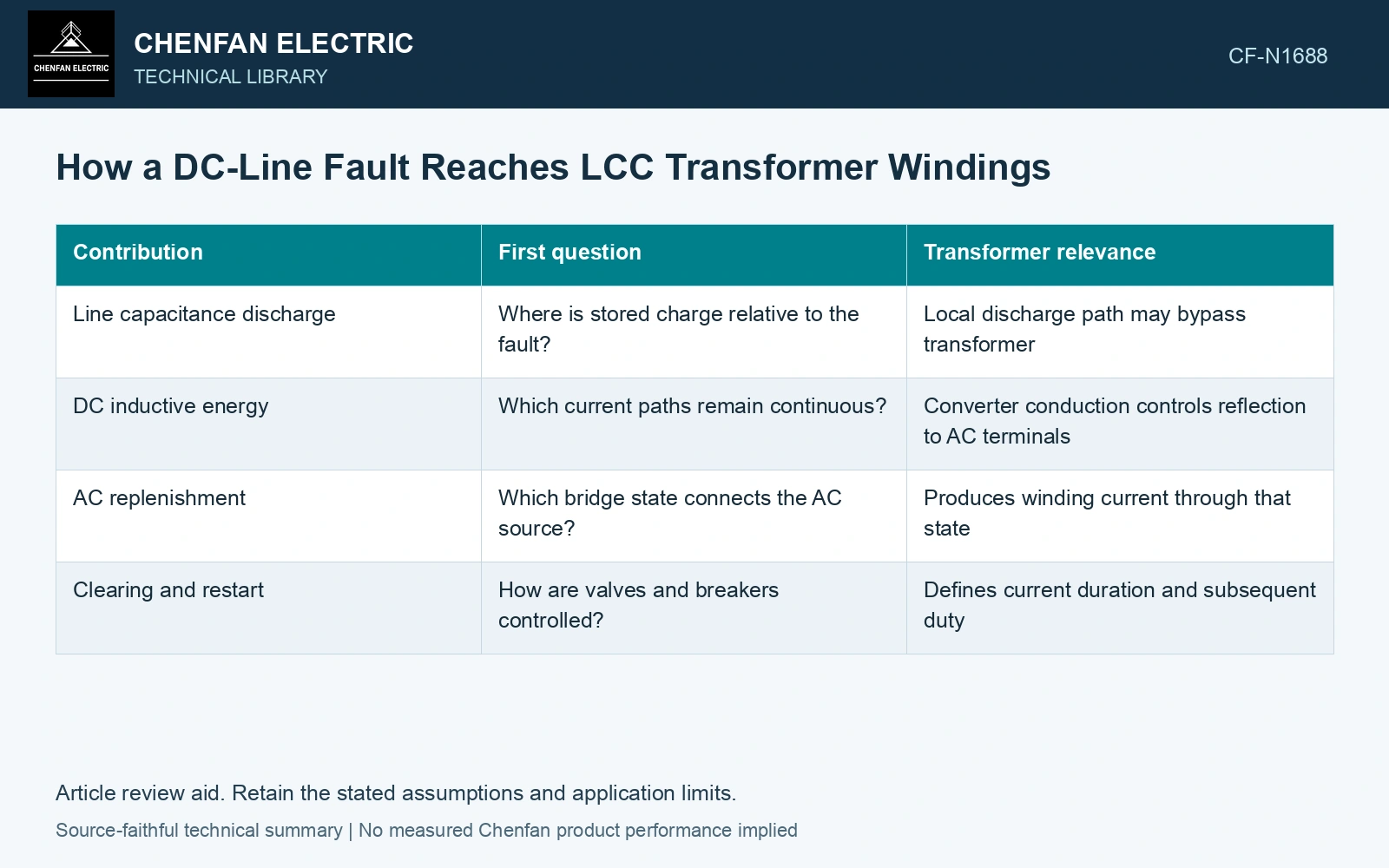
Partition the event by source
| Contribution | First question | Transformer relevance |
|---|---|---|
| Line capacitance discharge | Where is stored charge relative to the fault? | Local discharge path may bypass transformer |
| DC inductive energy | Which current paths remain continuous? | Converter conduction controls reflection to AC terminals |
| AC replenishment | Which bridge state connects the AC source? | Produces winding current through that state |
| Clearing and restart | How are valves and breakers controlled? | Defines current duration and subsequent duty |
For lumped screening, capacitor energy is ½CV² and inductor energy ½LI², using farads, volts, henries and amperes to obtain joules. A distributed line cannot generally be reduced to one capacitor for its fast transient waveform; travelling-wave effects and fault location matter.
The smoothing reactor changes rate of change
In an ideal lumped inductor, di/dt = v/L. The actual voltage across the smoothing reactor must come from the connected fault circuit, not the full pole voltage assigned by assumption. The reactor’s placement and any nonlinear behavior influence the current envelope.
Use the reconstructed valve currents to derive each transformer phase current. Keep initial DC current, AC system strength and converter control response in the case definition. Fault duration alone does not describe the winding peak or its asymmetry.
Account for stored energy without assigning its path
Assume a lumped 10 µF section initially at 300 kV and a 0.50 H reactor at 2 kA. Their stored energies are 0.45 MJ and 1.00 MJ respectively. If the actual reactor voltage is 50 kV for 5 ms, ΔI = VΔt/L = 500 A. Assigning the full 300 kV to that reactor instead predicts 3000 A, six times as much. Use the connected-circuit voltage and valve paths to decide which part reaches each transformer winding; neither energy total supplies that allocation.
Check the post-fault duty separately
Restart can impose another current sequence on a transformer that retains its pre-fault temperature and magnetic state. Record the blocking, clearing and recovery intervals rather than stopping the study at the first current maximum.
Follow the event from its DC energy source through the actual valve paths to synchronized winding currents. A local line-discharge peak becomes transformer duty only where that path transfers it. Keep the energy balance and terminal traces together when testing that inference.
Include normal converter operation and converter-side faults in the transformer transient study [2].
References
- IEC/IEEE, IEC/IEEE 60076-57-129:2017, Power transformers – Part 57-129: Transformers for HVDC applications.
- CIGRE WG B4.51, Technical Brochure 609, Study of Converter Transients Imposed on the HVDC Converter Transformers, 2015.