

An accessory receives motion through its actual tank/bracket support. FEMA identifies component/support/service-line load paths [1]; the mounting-point motion must therefore be represented separately from a generic ground input.
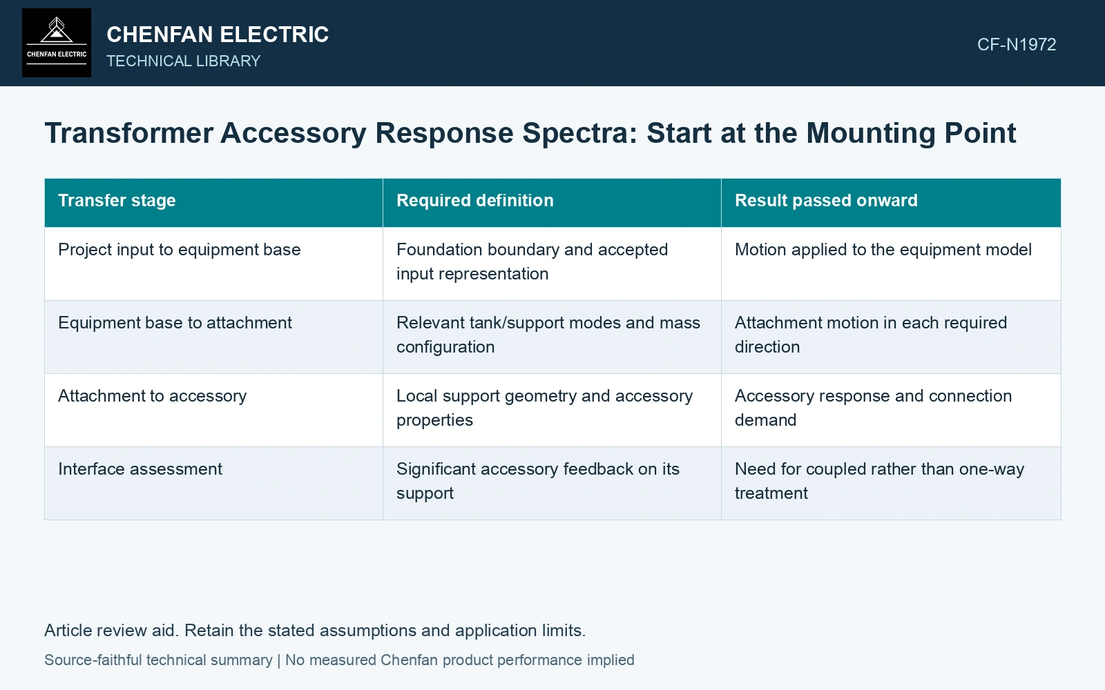
Identify the input location before comparing spectra
Record whether the project input is defined at the ground, foundation, equipment base or another interface. Then identify the accessory attachment coordinates and supporting structure. Installation height alone does not determine amplification; the tank and support modes also matter.
| Transfer stage | Required definition | Result passed onward |
|---|---|---|
| Project input to equipment base | Foundation boundary and accepted input representation | Motion applied to the equipment model |
| Equipment base to attachment | Relevant tank/support modes and mass configuration | Attachment motion in each required direction |
| Attachment to accessory | Local support geometry and accessory properties | Accessory response and connection demand |
| Interface assessment | Significant accessory feedback on its support | Need for coupled rather than one-way treatment |
A peak acceleration loses the frequency information
Two motions with the same peak acceleration can produce different responses in an accessory with a particular natural frequency and damping. A required response spectrum retains that frequency-dependent demand. Applying one peak acceleration to every accessory as a uniform static force can miss the mechanism the spectrum is intended to describe.
Derive or specify the mounting-point input using the accepted project method. Keep damping, axes, units and any spectrum-processing conventions with the result. Do not compare a spectrum evaluated at one damping value with a response based on another without the required treatment.
Check whether the accessory can be treated independently
A small accessory may permit an appropriate one-way transfer from support motion to local response. A substantial accessory or one close to a supporting-structure mode can influence that structure. Examine mass, stiffness and response sensitivity before accepting the uncoupled idealization.
NRC’s seismic-combination guide discusses multi-supported components whose support motions can differ [2]. Preserve relative support motion where it matters; one attachment spectrum does not reconstruct every multi-support interaction.
Assume ground peak acceleration 0.5g and a separately derived, fictional tank-roof response-spectrum ordinate 1.2g at an accessory’s frequency/damping. For assumed mass 50 kg and g = 9.81 m/s², force screens are 245.25/588.6 N, factor 2.4. Ground PGA cannot replace that mounting-point spectral input. Apply the compatible local input or coupled model, then check attachment demand and whether accessory feedback invalidates one-way transfer.
The accessory assessment should be traceable back through its attachment motion to the specified project input. Retain the configuration and directions at each stage. A mounting-height multiplier cannot replace this transfer unless its applicability has been established for the equipment and assessment method.
References
- FEMA and Applied Technology Council, FEMA E-74, Reducing the Risks of Nonstructural Earthquake Damage—A Practical Guide, December 2012, section 6.4.7.3, Transformers.
- U.S. Nuclear Regulatory Commission, Regulatory Guide 1.92, Combining Modal Responses and Spatial Components in Seismic Response Analysis, Revision 3, October 2012, sections C.1.1 and C.2.