

The vector group describes a terminal relationship. A repair shop needs something more detailed: which section starts at each terminal, which finish joins the next section, and how the path changes across taps. A damaged lead board can erase that information without changing anything readable on the nameplate. [1]
Treat the remaining winding as a circuit graph. Give every physical endpoint a temporary identity before assigning a phase or a function. A tag such as E17 is safer than calling an uncertain endpoint the neutral and allowing that guess to spread through the drawing.
Separate physical routes from electrical joins
Photographs should show both the endpoint and its route. Two leads passing beside one another are not evidence of a junction. A burned brazed joint may leave a mechanical shape that conceals several original branches. Record conductor size, strand grouping, insulation remnants and the section from which each lead emerges. Retain recovered joint pieces with their location identity.
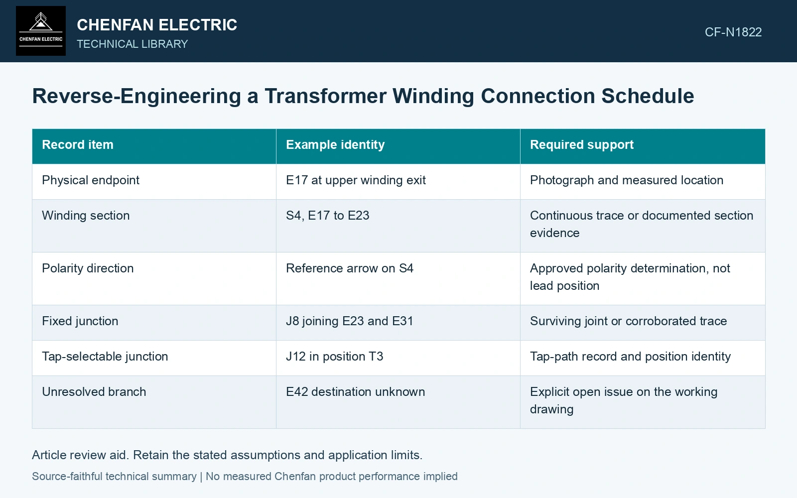
The working schedule can use directed edges. Each edge represents a known winding section, with a start, finish and polarity reference. Junctions become nodes. Connections established from a surviving joint receive a different confidence label from connections inferred from a ratio record. This keeps a neat circuit diagram from making uncertain evidence look certain.
| Record item | Example identity | Required support |
|---|---|---|
| Physical endpoint | E17 at upper winding exit | Photograph and measured location |
| Winding section | S4, E17 to E23 | Continuous trace or documented section evidence |
| Polarity direction | Reference arrow on S4 | Approved polarity determination, not lead position |
| Fixed junction | J8 joining E23 and E31 | Surviving joint or corroborated trace |
| Tap-selectable junction | J12 in position T3 | Tap-path record and position identity |
| Unresolved branch | E42 destination unknown | Explicit open issue on the working drawing |
Check the graph against terminal behavior
Every relevant tap must be checked against the graph. A schedule that explains the nominal position may still reverse a regulating section or assign its common lead incorrectly. Compare phase sequence, voltage magnitude and phase displacement using an approved test plan. Keep measured quantities distinct from the software’s interpreted vector-group label.
Use the actual winding connection, turns and common electrical reference when interpreting induced voltage, impedance and copper loss. [2]
Test a disputed section polarity
Assumptions: a disputed HV main path has 800 turns, the recovered series section 40 turns and the secondary 80 turns. The two polarity candidates give HV/LV ratios 840/80 = 10.5 and 760/80 = 9.5. With 800 V RMS, 50 Hz applied to the HV winding, predicted secondary readings are 76.19 and 84.21 V. An independently recorded secondary result of 76.2 V with an assumed ±0.2 V agreement interval fits the additive candidate and excludes the reversed candidate. Retain the additive hypothesis for this selected path, then confirm the endpoint trace, phase relationship and every other tap before issuing the schedule. A nominal vector-group label cannot supply those section identities. [1][2]
References
- U.S. Bureau of Reclamation, FIST Volume 3-31, Transformer Diagnostics, June 2003.
- U.S. Department of Energy, DOE-HDBK-1011/4-92, Electrical Science, Volume 4, 1992.