

A damaged winding may leave a clean terminal ratio record and almost nothing that can be counted. Those two facts do not determine its original construction. Several connection arrangements can produce similar terminal voltages, while parallel conductors can make a physical count look larger than the electrical turn count. [1]
The reconstruction should therefore begin with an evidence ledger. Record what survived before attempting to calculate what was lost. The transformer must be isolated and the work handled by qualified repair engineers; the ledger below is a design investigation, not an instruction for energizing damaged equipment.
Count electrical turns, not visible strands
A turn is a complete series path around the magnetic flux. Two conductors wound together and joined in parallel can occupy two visible positions while representing one turn. Conversely, a lead crossing the window may connect sections without adding the turn assumed from a photograph. Preserve start and finish identities, section boundaries, conductor transpositions and every surviving branch junction.
An intact phase can be valuable evidence, but only after checking that the phases were originally alike. Tap location, external lead routing and special phase-shifting sections can break that assumption. Mark a borrowed count as a hypothesis until another independent observation supports it.
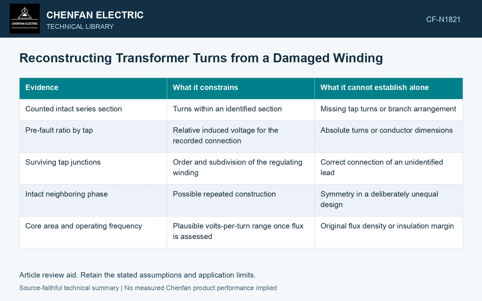
Make each observation constrain the same circuit
| Evidence | What it constrains | What it cannot establish alone |
|---|---|---|
| Counted intact series section | Turns within an identified section | Missing tap turns or branch arrangement |
| Pre-fault ratio by tap | Relative induced voltage for the recorded connection | Absolute turns or conductor dimensions |
| Surviving tap junctions | Order and subdivision of the regulating winding | Correct connection of an unidentified lead |
| Intact neighboring phase | Possible repeated construction | Symmetry in a deliberately unequal design |
| Core area and operating frequency | Plausible volts-per-turn range once flux is assessed | Original flux density or insulation margin |
An absolute turn count requires at least one independently identified series-turn population. Terminal ratios alone leave a scaling ambiguity, while physical strand counts must be reduced to their actual series/parallel circuit. Preserve that distinction before assigning a manufacturing count. [2]
Use the actual winding connection, turns and common electrical reference when interpreting induced voltage, impedance and copper loss. [2]
Resolve the counted-turn contradiction
Assumptions: an identified secondary has 40 series turns, and the correctly interpreted winding ratio at the recorded tap is 25, implying 1,000 primary turns. The surviving main winding contains 980 turns. Independent endpoint traces also identify two 10-turn regulating sections connected additively in that tested position. The complete path is 980 + 10 + 10 = 1,000 turns and predicts ratio 1,000/40 = 25. Retain that reconciled path for the tested position; counting only the main winding would omit 20 turns, or 2%. Verify the signed paths at every other tap before manufacturing. If the section traces were absent, the ratio would identify a contradiction without recovering its missing construction. [1][2]
References
- U.S. Bureau of Reclamation, FIST Volume 3-31, Transformer Diagnostics, June 2003.
- U.S. Department of Energy, DOE-HDBK-1011/4-92, Electrical Science, Volume 4, 1992.