

After an internal arc, blackened steel draws the eye. The visible mark may be deposited fault material, altered coating, a damaged steel surface or a mixture of all three. These conditions need different decisions. A photograph alone cannot distinguish them reliably, and its color cannot supply a percentage increase in core loss. [1]
The first useful output is a damage map. Divide it by lamination packet, face, depth accessible to inspection and distance from the suspected arc path. Record the condition before cleaning, because removing deposits may also remove evidence of their route. Investigation takes place on isolated equipment under a qualified repair plan.
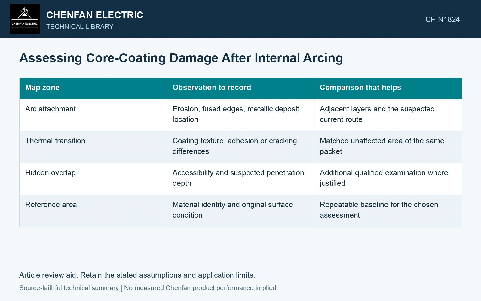
Use three nested zones
The direct arc zone contains visible erosion, fusion or deposited metal. Around it is a transition zone where heat or contamination may have altered an interface without dramatic surface damage. Beyond that lies a reference zone selected for comparable steel, coating and assembly history. A distant shiny area is a weak reference if it comes from a different material lot or endured different handling.
| Map zone | Observation to record | Comparison that helps |
|---|---|---|
| Arc attachment | Erosion, fused edges, metallic deposit location | Adjacent layers and the suspected current route |
| Thermal transition | Coating texture, adhesion or cracking differences | Matched unaffected area of the same packet |
| Hidden overlap | Accessibility and suspected penetration depth | Additional qualified examination where justified |
| Reference area | Material identity and original surface condition | Repeatable baseline for the chosen assessment |
A sample location should be chosen to answer a question. Sampling the most dramatic mark may show severe local damage while missing the transition boundary that determines how much material needs removal. Conversely, taking only convenient surface pieces can leave the deepest affected interfaces unexamined. Record these accessibility limits on the map.
Separate coating evidence from magnetic evidence
The coating helps control electrical contact between laminations. A damaged interface may allow current paths, but the resulting heating depends on the geometry and excitation of the connected path. One exposed scratch does not determine the behavior of the assembled core. Arc-related stress and disturbed joints can also change magnetic behavior without producing the same surface appearance.
For that reason, a material examination and a completed-core magnetic check serve different purposes. The first characterizes the affected zone; the second measures the assembled consequence under its recorded conditions. Neither should be used to invent the other’s missing result. If a coating test is proposed, its specimen preparation must preserve the interface relevant to the question.
Surface insulation resistance is a lamination-interface measurement; its defined specimen boundary does not establish assembled-core loss or every unintended metallic path. [2]
Separate coating screening from assembled loss
Nippon Steel lists 23ZH85 maximum new-strip loss of 0.85 W/kg at 1.7 T, 50 Hz. [3] Assumptions: identified steel mass is 800 kg, giving a 680 W catalogue basis, and the project assembled-core loss budget is 1.25 times this basis, or 850 W. A matched test at the same stated excitation rises from 800 to 920 W after the arc/repair sequence: +120 W, or 15%, and 70 W above the assumed budget. Hold assembly reuse pending investigation. Separately, assume matched coating specimens tested under one qualified voltage/contact setup draw 1 mA in the reference zone and 20 mA in the transition zone; that is twentyfold conductance, and exceeds an assumed 5 mA project specimen gate by 15 mA. Expand the mapped coating investigation through that transition zone. These two failures establish different concerns; neither a scratch count nor total loss uniquely attributes heating to coating damage. [1][2]
Interlaminar insulation, burr height, arc deposits, lamination flatness and clamp load govern contact paths. The transition zone needs its own evidence because visible erosion does not define the complete thermally affected boundary.
References
- U.S. Bureau of Reclamation, FIST Volume 3-31, Transformer Diagnostics, June 2003.
- IEC, IEC 60404-11:2021, Magnetic materials — Part 11: Methods of measurement of the surface insulation resistance of electrical steel strip and sheet.
- Nippon Steel Corporation, Grain-Oriented Electrical Steel Sheets, catalogue D004je, April 2020, specification and typical-property tables.