

Carry pressboard fibre direction from the parent sheet through nesting, machining and installation. This coordinate record keeps the finished part’s material axes aligned with its specified mechanical duty.
Oria and colleagues report manufacturing properties and compression tests for a particular 2 mm high-density pressboard [1]. Their table distinguishes MD and CD tensile strength; that strength is not a machined-part design allowable.
Carry the sheet coordinates into the drawing
Define MD and CD on the parent sheet before cutting. Do not infer MD from the sheet’s longest dimension unless the supplier explicitly establishes that relationship. Give the sheet face an identifier as well, so a flipped nest does not become an undocumented change in the orientation record.
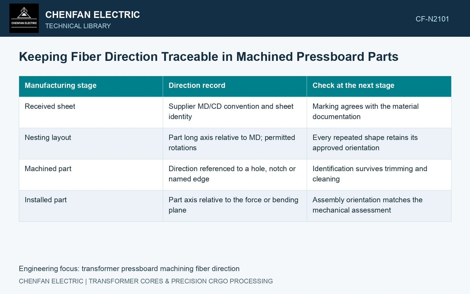
| Manufacturing stage | Direction record | Check at the next stage |
|---|---|---|
| Received sheet | Supplier MD/CD convention and sheet identity | Marking agrees with the material documentation |
| Nesting layout | Part long axis relative to MD; permitted rotations | Every repeated shape retains its approved orientation |
| Machined part | Direction referenced to a hole, notch or named edge | Identification survives trimming and cleaning |
| Installed part | Part axis relative to the force or bending plane | Assembly orientation matches the mechanical assessment |
For an illustrative rectangular part, a long axis initially parallel to MD becomes parallel to CD after a 90-degree nest rotation. Its thickness direction is unchanged. The two versions therefore require comparison for an in-plane tensile or bending duty, while an axial compression assessment must address the thickness direction and contact conditions.
Test the load that the geometry creates
A plain strip, a notched strip and a drilled support need different witnesses. A notch can place the critical ligament across the sheet direction even when the overall part length follows MD. A hole may introduce local bearing or splitting that a longitudinal tensile strip never exercises.
IEC 60641-2 concerns test methods for non-laminated pressboard and presspaper [2]. Match the starting material and test direction before carrying its data into a part assessment. Compare the permitted cutting orientations using the same batch, conditioning state and representative loading fixture; record where damage starts, not only maximum load.
Direction marking should not introduce an unqualified ink, label adhesive or loose contaminant into an oil-filled assembly. A controlled nest record, protected offcut reference and approved part identification method can preserve the mapping without leaving unsuitable marking material on the finished insulation.
Oria’s Table 1 lists tensile strength of 124 MPa in MD and 92 MPa in CD for its particular nominal 2 mm pressboard [1]. Assume a 2.0 kN purely tensile load, a 25 × 2 mm undamaged net ligament, identical conditioning and a teaching screening factor of 3 applied to those strengths. Stress is 40 MPa. The assumed design screens become 41.33 MPa in MD and 30.67 MPa in CD; utilisation is 0.968 or 1.304. The 90° rotation therefore fails that assumed CD screen, while MD only narrowly passes. Preserve MD for the next representative qualification test; do not release a drilled/notched part from these manufacturer strength values. Obtain batch-specific directional evidence and the approved design allowable for the actual moisture, temperature and stress concentration.
State permitted rotations for each part family on the purchasing drawing. Set that allowance from directional deformation and representative load tests, then give nesting the approved orientation range.
References
- C. Oria et al., Experimental dataset on the compressive mechanical properties of high-density pressboard used in power transformers spacers, Data in Brief 50, 109471, 2023. DOI: 10.1016/j.dib.2023.109471.
- IEC, IEC 60641-2:2004, Pressboard and presspaper for electrical purposes — Part 2: Methods of tests.