

Pressboard angle-ring qualification must examine the heel where the flange turns into the collar. Registered sections expose folds and internal separation behind a smooth outer face. [1]
Calculation basis. Project-specific values and gates in the illustrative screens below are assumptions; cited catalogue values retain their source test conditions.
Start by identifying the actual construction. Drawn or moulded cellulose board, pressed sectors and flexible laminated crepe-paper rings are different products. A forming method demonstrated for one family cannot be assigned to another by matching its finished dimensions.
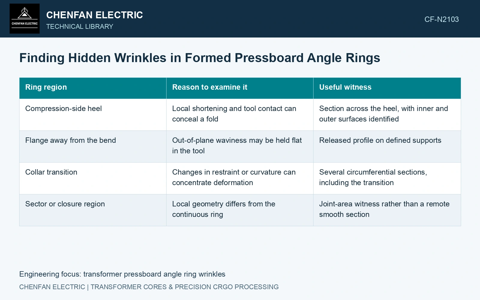
Map the regions that must accommodate shortening
During bending, the inner side of the thickness follows a shorter path than the outer side. Ring forming can also impose unequal circumferential deformation as material moves between the flange and collar. Whether the material accommodates that deformation smoothly depends on the blank, support and qualified forming state.
| Ring region | Reason to examine it | Useful witness |
|---|---|---|
| Compression-side heel | Local shortening and tool contact can conceal a fold | Section across the heel, with inner and outer surfaces identified |
| Flange away from the bend | Out-of-plane waviness may be held flat in the tool | Released profile on defined supports |
| Collar transition | Changes in restraint or curvature can concentrate deformation | Several circumferential sections, including the transition |
| Sector or closure region | Local geometry differs from the continuous ring | Joint-area witness rather than a remote smooth section |
Use it to select where a qualification part is examined, rather than cutting one convenient section and calling the entire ring sound.
Compare the tool-held and released shapes
A formed component should be observed after the specified release and conditioning sequence. Tool pressure can flatten a wrinkle temporarily. Conversely, uncontrolled storage can add distortion that was absent when the part left the process. Record material batch, blank orientation, forming-route revision and the interval between release and inspection.
The significance of material state is supported by pressboard compression experiments showing that moisture, temperature and precompression history affect mechanical response. Those experiments do not establish a wet-forming recipe. A process change needs a part-specific trial, including checks for dimensional stability and internal damage.
Unfolding a sacrificial witness can expose a concealed fold, but it may also straighten, tear or create damage. Photograph the original shape first. Mark the intended section locations, document the opening procedure and use an intact adjacent section to distinguish a pre-existing defect from damage introduced during examination.
A visual grading reference should include folds, waviness, layer separation and tool impressions as separate features. A shallow smooth impression is not automatically equivalent to a closed crease with separated layers. Relate each category to its actual location, contact pressure, oil access and electrical duty.
For each new ring size, place destructive witnesses at the severe curvature and geometry transitions. Use those regions to define the dimensional range supported by the forming process.
Use the local wrinkle height in the assembly envelope
Keep conditioning, loading direction and aging state with pressboard comparisons [2]. Finished insulation acceptance must retain the actual winding-terminal dielectric boundary [3].
Assume an angle ring has 3.0 mm nominal wall, a concealed 0.6 mm wrinkle and 0.2 mm geometric runout toward the same interface. The local envelope is 3.8 mm, consuming 0.8 mm more than nominal. Against an assumed 1.0 mm oil-gap allowance, only 0.2 mm remains. Assume the drawing requires at least 0.4 mm remaining at that interface. The calculated 0.2 mm fails by 0.2 mm. Rework or reject the geometry and inspect the hidden heel in the defined support state before repeating the assembly and dielectric checks.
References
- IEC, IEC 60641-2:2004, Pressboard and presspaper for electrical purposes — Part 2: Methods of tests.
- C. Oria, I. Carrascal, D. Ferreño, C. Méndez and A. Ortiz, Experimental dataset on the compressive mechanical properties of high-density pressboard used in power transformers spacers, Data in Brief 50, 109471, 2023. DOI: 10.1016/j.dib.2023.109471.
- IEC, IEC 60076-3:2013+AMD1:2018, Power transformers — Part 3: Insulation levels, dielectric tests and external clearances in air.