

A no-load test can heat the core and induce losses in nearby clamps. Separate structural sources from transferred core heat to locate the mechanism governing each measured temperature. [1] [2]
Measuring the clamp alone cannot establish the core temperature or the origin of the heat. Use paired locations and an explicit description of the interface.
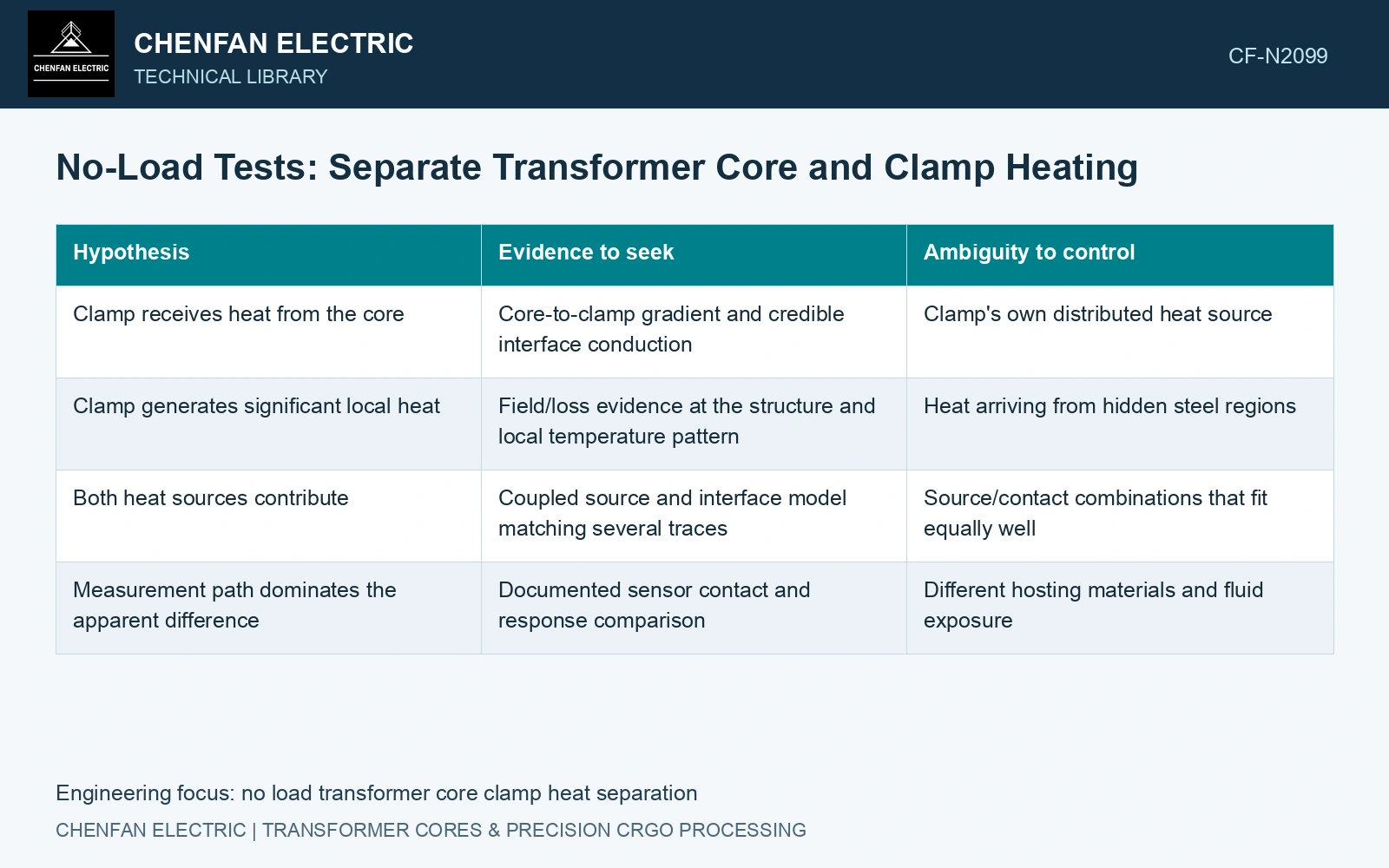
Arrange the measurements around the contact path
Record a steel point near the contact, a clamp point near it, an exposed clamp region and the relevant local fluid temperature. Where possible, include a steel comparison point away from the contact but with a known thermal role.
| Hypothesis | Evidence to seek | Ambiguity to control |
|---|---|---|
| Clamp receives heat from the core | Core-to-clamp gradient and credible interface conduction | Clamp’s own distributed heat source |
| Clamp generates significant local heat | Field/loss evidence at the structure and local temperature pattern | Heat arriving from hidden steel regions |
| Both heat sources contribute | Coupled source and interface model matching several traces | Source/contact combinations that fit equally well |
| Measurement path dominates the apparent difference | Documented sensor contact and response comparison | Different hosting materials and fluid exposure |
Keep electrical and thermal evidence distinct
Terminal no-load loss includes the sources within its measurement boundary. It does not directly partition watts between the core and clamp. Subtracting a theoretical core loss to obtain clamp loss can leave the difference dominated by uncertainty or omitted sources.
A field model can estimate induced-current heating in the clamp, provided its material, conductive paths and magnetic coupling are represented. A model that only assigns material loss to the core cannot explain a structural hot spot by adjusting the clamp’s thermal conductivity.
Separate the source from the contact path in the thermal model. Perfect contact, insulating contact and a measured finite conductance produce different gradients for the same source pair.
Use controlled characterization where needed
In an approved representative construction, independent thermal input to a de-energized component can help characterize heat transfer and sensor response. State which boundaries differ from the magnetic test. Removing a clamp or changing its contact pressure is not an isolated source experiment if it also changes core geometry and magnetic behaviour.
Compare heating and cooling histories with measured surrounding temperatures. A clamp that responds first is suggestive evidence, but sensor lag and unequal conduction paths can create the same timing. Confirm the explanation with the spatial pattern and forward-model prediction.
Nippon Steel lists a maximum specific loss of 0.90 W/kg for 0.23 mm 23ZH90 at 1.7 T and 50 Hz. [3] Assume 1,000 kg of steel and 1,100 W terminal no-load input at that excitation. The 900 W strip budget leaves 200 W unallocated; joints, processing and other sources prevent assigning it to clamps. Also assume clamp-to-core conductance 8 W/K and a 6 K temperature difference, giving 48 W transferred heat. That transfer is separate from induced clamp heating. Use additional spatial and field evidence to close the unallocated input rather than count the same transferred heat twice.
Control cut-edge burr, joint gap, packet alignment and clamp pressure together: each can change the magnetic source or the contact heat path. Preserve their assembly records when comparing no-load temperature maps.
Report supported core and clamp heat-source contributions and retain their separate temperature results. Identify unresolved combinations and the interface evidence needed to choose the remedy.
References
- Z. Chen, Z. He and S. Wang, Transformer Iron Core Temperature Field Calculation Based on Finite Element Analysis, Energies 18, 6537, 2025. DOI: 10.3390/en18246537.
- U.S. Department of Energy, DOE-HDBK-1012/2-92, Thermodynamics, Heat Transfer, and Fluid Flow, Volume 2, 1992.
- Nippon Steel Corporation, Grain-Oriented Electrical Steel Sheets, catalogue D004je, April 2020, specification and typical-property tables.