

Pressboard kits must identify the winding interface, handedness and drawing revision of each piece. Use that interface map with the count to place every barrier in its intended assembly position. [1]
Calculation basis. Project-specific values and gates in the illustrative screens below are assumptions; cited catalogue values retain their source test conditions.
Build the kit from the released assembly hierarchy. Each item should connect to a winding or interface, a stage in the build and a defined orientation. The relationship is more informative than a list arranged only by part size.
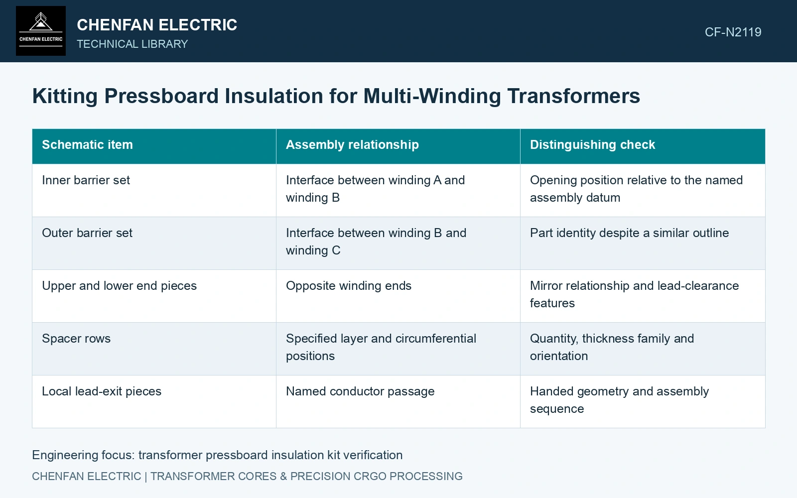
A part-to-assembly map
| Schematic item | Assembly relationship | Distinguishing check |
|---|---|---|
| Inner barrier set | Interface between winding A and winding B | Opening position relative to the named assembly datum |
| Outer barrier set | Interface between winding B and winding C | Part identity despite a similar outline |
| Upper and lower end pieces | Opposite winding ends | Mirror relationship and lead-clearance features |
| Spacer rows | Specified layer and circumferential positions | Quantity, thickness family and orientation |
| Local lead-exit pieces | Named conductor passage | Handed geometry and assembly sequence |
The labels above are illustrative. The actual map must come from the transformer design, including any differences between phase positions. Do not infer interchangeability because two parts fit within the same packaging footprint.
Make mirror errors visible before packing
Check parts in a common orientation against a named edge, face or opening. “Left” and “right” without the viewing direction are ambiguous. A mirrored part can match the overall width and height while placing a notch beside the wrong conductor.
Where sheet direction is specified, include it in the kit reference. If the part must be flipped during assembly, identify both its material orientation and the functional face. An installation sketch can resolve relationships that a part label alone leaves unclear.
Use a revision matrix linking the assembly drawing, detail drawings and applicable material specification. Reworked or substituted pieces need the same relationship checked; adding a current label to an older geometry does not make it conform to the revision.
Arrange subkits according to the build sequence and inspect their completeness before enclosure. A part needed under another component can become inaccessible later. Record its presence at the point where the sequence still permits correction.
Keep similar-but-different families physically distinguishable using an approved packaging method. Avoid marking or adhesive materials that have not been accepted for the insulation route. Packaging should preserve identification without adding fibers, residue or an unsuitable substance to the parts.
The kit inspection should include condition as well as identity: damaged edges, distortion and foreign material can arise after individual part acceptance. Record how protected parts move from inspection to the assembly station so those checks remain meaningful.
A missing item and a wrong-handed item demand different corrections. The interface map lets the assembler identify the affected location and the exact replacement needed, rather than discover an unexplained mismatch after several windings have been built.
Check kit identity before counting completeness
Configuration identity and drawing revision must remain tied to each physical kit item [2].
Assume a winding assembly needs 120 identified spacers. A kit contains 120 pieces, but five belong to the wrong thickness code. Physical count is 100% while correct-item coverage is 115/120 = 95.83%. Assume those five positions require a 4.0 mm duct height but received 3.0 mm spacers; each affected local gap is 25% lower. Resolve their identities and revisions before issue rather than accepting the 95.83% total-item score.
References
- IEC, IEC 60641-2:2004, Pressboard and presspaper for electrical purposes — Part 2: Methods of tests.
- NASA, NASA Systems Engineering Handbook, section 6.5, Configuration Management, official online text.