

Pressboard cutter wear should be tracked against slot width, corner integrity and particle shedding. Measure those quality trends through the run to establish an observable tool-replacement trigger. [1]
Calculation basis. Project-specific values and gates in the illustrative screens below are assumptions; cited catalogue values retain their source test conditions.
Track several outputs that can respond differently. A slot may retain its measured width while its edge begins to shed material. Another may remain visually neat while its root profile moves outside the intended geometry.
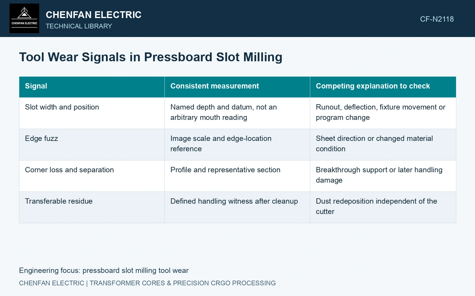
Build a trend around the critical features
| Signal | Consistent measurement | Competing explanation to check |
|---|---|---|
| Slot width and position | Named depth and datum, not an arbitrary mouth reading | Runout, deflection, fixture movement or program change |
| Edge fuzz | Image scale and edge-location reference | Sheet direction or changed material condition |
| Corner loss and separation | Profile and representative section | Breakthrough support or later handling damage |
| Transferable residue | Defined handling witness after cleanup | Dust redeposition independent of the cutter |
Record tool identity, time or cutting exposure, part sequence and material batch with each observation. For mixed geometries, piece count alone hides differences in cut length, engagement and the number of features machined.
Do not assume wear always makes a slot narrower. Reduced effective cutting geometry, runout, elastic deflection and damaged edges can influence the measured result in different directions. The trend describes the product; examining the tool and setup helps identify its cause.
Use comparisons that can separate causes
Retain a baseline from a known acceptable tool and qualified setup. Periodic witness features should match the production material direction and relevant geometry. A convenient soft or thin coupon can be easier to machine and may miss the decline affecting a thick support.
When a new tool is installed, compare the affected signals under otherwise comparable conditions. Improvement supports a tool-related explanation, but a simultaneous material or fixture change prevents that comparison from isolating wear.
Inspect parts near the end of the proposed interval, including critical slot ends and internal corners. Repeating only a mouth-width measurement cannot establish that the entire slot remains within the qualified edge and wall condition.
Choose tool-change criteria from the dimensions, edge damage and cleanliness evidence that govern use of the part. A dimensional warning level may be appropriate for one signal, while a distinct defect category controls another. Preserve both rather than averaging them into a score that can conceal damage.
A count-based replacement interval can be used once its coverage is demonstrated for a defined family and operating range. It should be revised when the material, geometry or cutting route changes enough to alter exposure.
Keep the replacement decision close to the observable mechanism: an established width drift, unacceptable corner damage or a repeatable rise in shedding. “Replace every fixed number of pieces” is useful only when that number follows those observations and their variation.
Separate tool-wear drift from thickness variation
Keep measurement variation and the comparison interval with a dimensional decision [2].
Assume a defined slot-width measurement falls from 8.00 mm with a fresh tool to 7.86 mm at the proposed wear endpoint, at matched material conditioning. Drift is −0.14 mm. Against an assumed 7.90 mm minimum drawing limit, the endpoint is 0.04 mm short. Assume an absolute ±0.03 mm comparison interval: even the upper endpoint, 7.89 mm, remains below 7.90 mm. Hold that condition and establish an earlier trigger from the validated wear trend, measurement capability and separate shedding/corner checks.
References
- IEC, IEC 60641-2:2004, Pressboard and presspaper for electrical purposes — Part 2: Methods of tests.
- B. N. Taylor and C. E. Kuyatt, NIST Technical Note 1297, Guidelines for Evaluating and Expressing the Uncertainty of NIST Measurement Results, 1994 edition.