

A pressboard cylinder scarf joint needs a controlled finished wall section. Allocate taper, registration and bond-layer tolerances against the adjoining oil gap to qualify the seam’s actual geometry. [1]
Calculation basis. Project-specific values and gates in the illustrative screens below are assumptions; cited catalogue values retain their source test conditions.
Inspect the joint against a defined cylinder datum. If the assembly locates the inner surface, an outer ridge affects one neighbouring gap. If both surfaces are allowed to move, the displacement must be distributed according to the real supports. Reporting only the average cylinder wall thickness misses this distinction.
Write the section before setting the overlap tolerance
At a position x through the overlap, the local wall is the sum of the two residual taper thicknesses and any bond layer: h(x) = t₁(x) + t₂(x) + b(x). Compare that wall with the specified parent thickness and check the two taper ends separately. The adhesive system, where used, requires its own oil-compatibility and process qualification.
For an illustrative ideal pair of complementary linear tapers, a registration error δ adds approximately tδ/L to the combined thickness over the region where both tapers overlap. Here t is parent thickness and L is taper length; this approximation does not describe the discontinuities at the taper ends.
With fictional dimensions t = 4 mm, L = 20 mm, δ = 0.5 mm and a uniform bond layer of 0.1 mm, the overlap wall becomes 4 + 4 × 0.5/20 + 0.1 = 4.2 mm. The excess is 0.2 mm. If the inner surface is fixed and the nominal outer oil gap is 0.8 mm, that particular section leaves 0.6 mm before adding other assembly errors. These are geometry calculations, not acceptable insulation distances.
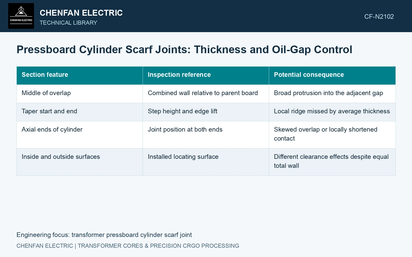
| Section feature | Inspection reference | Potential consequence |
|---|---|---|
| Middle of overlap | Combined wall relative to parent board | Broad protrusion into the adjacent gap |
| Taper start and end | Step height and edge lift | Local ridge missed by average thickness |
| Axial ends of cylinder | Joint position at both ends | Skewed overlap or locally shortened contact |
| Inside and outside surfaces | Installed locating surface | Different clearance effects despite equal total wall |
Measure a joint that represents the delivered state
Use a restrained measurement arrangement that reproduces the intended cylinder shape without forcibly flattening the joint. Record the conditioning state and measuring force. A seam pressed flat by the inspection fixture may spring up after unloading or change again during subsequent processing.
Qualification sections from representative joints reveal taper mismatch, pockets and discontinuous bonding that surface measurements cannot resolve. They supplement inspection of the finished cylinders; they do not justify assuming that every joint has the section found in one witness.
Select overlap from mechanical and electrical evidence, then control taper form, registration and bond thickness. Verify the finished wall and adjoining oil space together.
Carry scarf misregistration into the remaining oil gap
Keep conditioning, loading direction and aging state with pressboard comparisons [2]. Finished insulation acceptance must retain the actual winding-terminal dielectric boundary [3].
For assumed 4 mm stock, 20 mm scarf length, 0.5 mm registration error and 0.1 mm bond layer, local wall is 4.2 mm. The 0.2 mm excess reduces an assumed 0.8 mm oil gap to 0.6 mm, a 25% reduction. Assume forming and support consume another 0.05 mm and the qualified drawing requires at least 0.65 mm at this interface. Remaining gap is 0.55 mm, failing by 0.10 mm. Reduce the combined seam and locating contributions, then verify the full dielectric geometry; testing the parent board cannot release this seam.
References
- IEC, IEC 60641-2:2004, Pressboard and presspaper for electrical purposes — Part 2: Methods of tests.
- C. Oria, I. Carrascal, D. Ferreño, C. Méndez and A. Ortiz, Experimental dataset on the compressive mechanical properties of high-density pressboard used in power transformers spacers, Data in Brief 50, 109471, 2023. DOI: 10.1016/j.dib.2023.109471.
- IEC, IEC 60076-3:2013+AMD1:2018, Power transformers — Part 3: Insulation levels, dielectric tests and external clearances in air.