

A pre-assembled core thermal test qualifies a defined excitation and cooling envelope. Use it to expose joint or clamp heating before final assembly, then carry those findings into complete-transformer verification.
The completed transformer adds winding heat, changed circulation, tank surfaces and structural contacts. Passing the earlier core test does not establish that the completed unit meets its temperature-rise requirements.
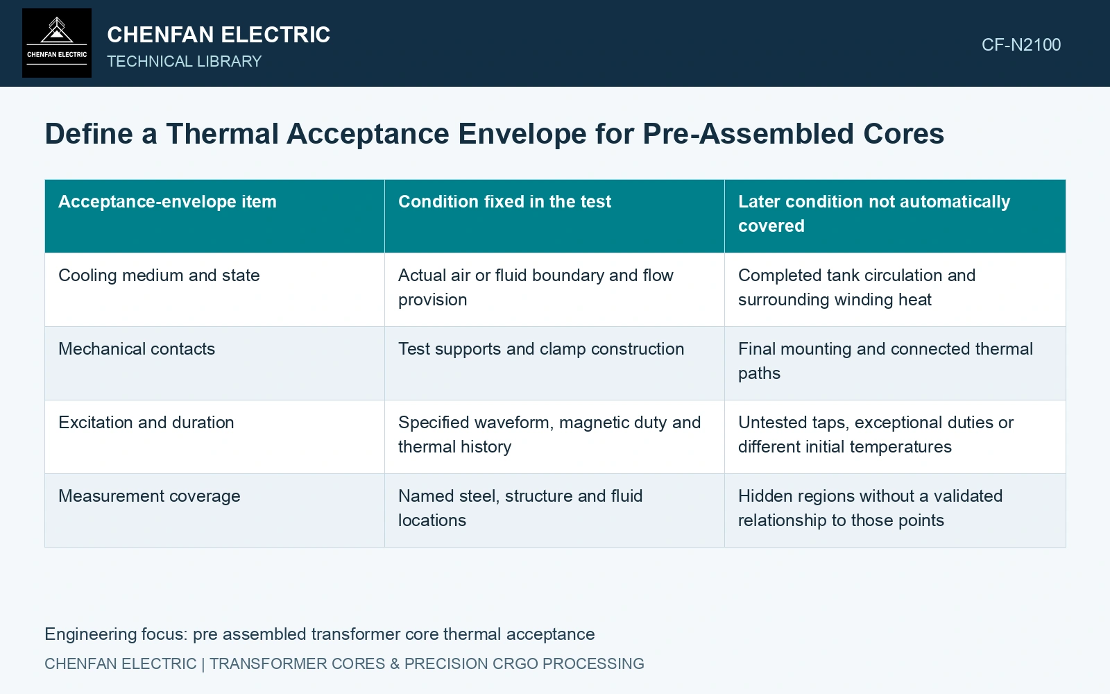
Specify the tested construction
Identify the material and processing state, packet schedule, joints, clamps, supports and any cooling ducts. Record temporary excitation windings and fixtures because they can change the heat source and cooling access.
Define voltage, frequency, waveform and active turns, including the method used to establish equivalent magnetic duty. A temporary winding arrangement that changes local fields can affect nearby structural heating even when average core flux is similar.
| Acceptance-envelope item | Condition fixed in the test | Later condition not automatically covered |
|---|---|---|
| Cooling medium and state | Actual air or fluid boundary and flow provision | Completed tank circulation and surrounding winding heat |
| Mechanical contacts | Test supports and clamp construction | Final mounting and connected thermal paths |
| Excitation and duration | Specified waveform, magnetic duty and thermal history | Untested taps, exceptional duties or different initial temperatures |
| Measurement coverage | Named steel, structure and fluid locations | Hidden regions without a validated relationship to those points |
Define what constitutes a thermal pass
Agree the relevant absolute temperatures or rises, their reference locations, duration or stabilization basis, measurement uncertainty and decision rule. Those values must follow the intended materials and equipment requirements; a generic core article cannot supply a universal limit.
Retain the maximum observed location, not only an average. Identify inaccessible regions and the model evidence used to bound them. A support temperature should not be labelled steel temperature without a verified transfer relation.
If a transient criterion is used, record the initial thermal state and endpoint. If a steady-state claim is made, support it from the actual trace and boundary stability rather than an arbitrary elapsed time.
Carry the boundary into the purchase result
Report the tested envelope with the pass statement: construction, duty, cooling and measurement coverage. List the completed-unit interactions requiring later validation. IEC 60076-2 covers temperature rise for liquid-immersed transformers. Define the separate test boundary and subsequent complete-transformer verification explicitly when using a bare or pre-assembled core screen. [1]
Use steel data to size the test heat budget
Use an explicit heat-source and cooling-resistance model [2]; temperature-dependent magnetic properties can require iteration with the thermal solution [3].
Nippon Steel specifies 0.23 mm 23ZH85 at maximum 0.85 W/kg and 23ZH90 at 0.90 W/kg, both at 1.7 T and 50 Hz under catalogue specimen conditions [4]. For an assumed 500 kg strip mass, the corresponding loss budgets are 425 W and 450 W, a 25 W difference. Assume a lumped 0.040 K/W thermal resistance at this test boundary; strip-only rises are 17 K and 18 K. Now assume the assembled construction adds 50 W and that a 1 K upper comparison allowance covers the temperature estimate. The resulting upper rises are (425+50)×0.040+1 = 20 K and (450+50)×0.040+1 = 21 K. Against an assumed 20 K project allocation, the first case reaches its boundary and the second exceeds it by 1 K. Establish the actual assembled loss and local temperatures before choosing the steel or releasing the core: a lumped result cannot establish the hottest clamp or the completed transformer. Joint overlap, burrs, residual cutting stress and clamp pressure control departures from the strip baseline; winding and tank heat belong to subsequent complete-transformer verification.
References
- IEC, IEC 60076-2:2011, Power transformers — Part 2: Temperature rise for liquid-immersed transformers.
- U.S. Department of Energy, DOE-HDBK-1012/2-92, Thermodynamics, Heat Transfer, and Fluid Flow, Volume 2, 1992.
- Z. Wang, K. Xu and Y. Du, Temperature Rise Calculation of Magnetic Core Considering the Temperature Effect of Magnetic Properties in an Electrical Steel Sheet, Symmetry 14, 2315, 2022. DOI: 10.3390/sym14112315.
- Nippon Steel Corporation, Grain-Oriented Electrical Steel Sheets, catalogue D004je, April 2020, specification and typical-property tables.