

Multiple core grounds should be investigated by reconstructing the conductive paths and their magnetic coupling before drawing a fault conclusion from one current reading. An unintended second connection can create a loop, but the resulting current and heating depend on the loop impedance, linked flux and operating state. There is no universal current value that diagnoses every assembly.
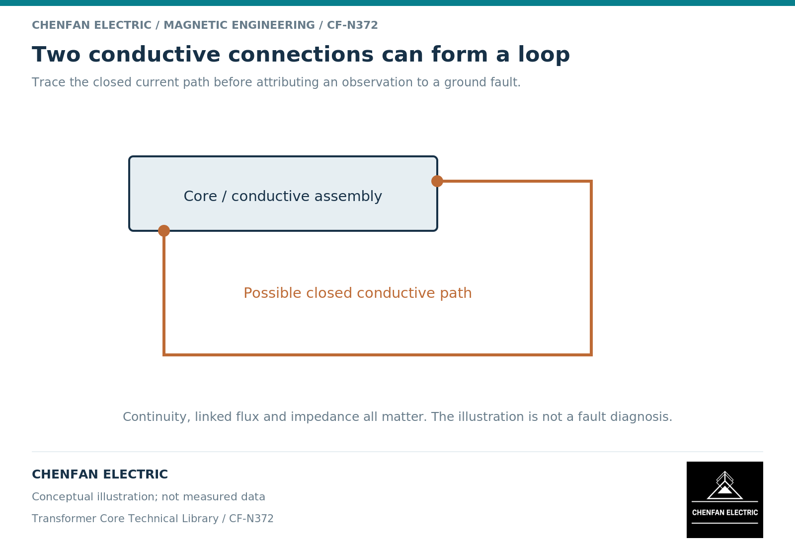
Establish whether two paths actually exist
Begin with the intended electrical node map. Identify the designated core-ground connection, the surrounding clamps and tank, and the interfaces intended to remain insulated. Then distinguish an observed additional connection from a suspected one.
A conductive route can pass through several components and contacts. A drawing omission, a temporary assembly component and a permanent unintended contact are different findings. Their consequences must be evaluated in the relevant final configuration.
Core-grounding research describes both capacitive current paths and abnormal grounding concerns. [1] Its equipment-specific examples should not be converted into a universal alarm threshold or a diagnosis for an unidentified transformer.
Connect the loop to its source
For a closed loop, the induced electromotive force depends on the time derivative of the linked magnetic flux. [2] The current then depends on the complete electrical impedance and electromagnetic interaction with the source.
This means that connection location matters. Two routes linking different field regions need not carry the same current. Load-related leakage fields, magnetic excitation and harmonic content may all affect the observation.
A change in current with load can help distinguish hypotheses, but correlation alone does not identify the exact contact. A capacitive contribution can also change with the operating voltage and waveform. Retain the full operating record instead of assigning one mechanism solely from a trend.
Treat measurements as evidence with a configuration
| Observation | What remains to be established |
|---|---|
| Elevated ground-lead current | Sensor validity, spectrum and operating baseline |
| Low resistance between identified nodes | Whether that connection is intended in the tested state |
| Local heating | Its electrical source and thermal path |
| Intermittent signal | Connection stability, interference and operating changes |
| Change after assembly | Which new interface changed the electrical network |
A sensor around the designated lead observes that path, not every possible circulating current elsewhere in the assembly. If current divides between parallel paths, the reading in one path need not equal the total relevant current.
Likewise, a high insulation-resistance result under one documented test configuration does not prove that every local interlaminar path is absent. Test object and failure hypothesis must match.
Close the diagnosis without unsafe shortcuts
The investigation record should state the intended topology, observed deviations, measurement configuration, operating cases and competing explanations. Separate confirmed findings from provisional hypotheses and assign each unresolved item to a responsible reviewer.
Do not disconnect the designated ground, alter hardware or insert improvised insulation on the basis of a general article. Such work changes an electrical safety and functional boundary and requires the transformer’s approved process.
A defensible conclusion identifies the unwanted path and explains why it produces the observed behavior, or states which evidence remains insufficient. That is materially stronger than labeling a transformer faulty from one unexplained current number or declaring it healthy because one monitored lead carries little current.
References
[1] Xiu Zhou and coauthors / Frontiers in Energy Research. Analytical modeling and calculation of core grounding current in converter transformer (2023).
[2] Lloyd Dixon / Texas Instruments. Magnetics Design 1 – Introduction and Basic Magnetics.