

Core-to-clamp insulation is an assembly interface, not another name for the coating between electrical-steel laminations. It separates designated conductive parts according to the transformer’s grounding design. Its acceptance evidence must therefore identify the core, clamp and surrounding connections in the actual tested state.
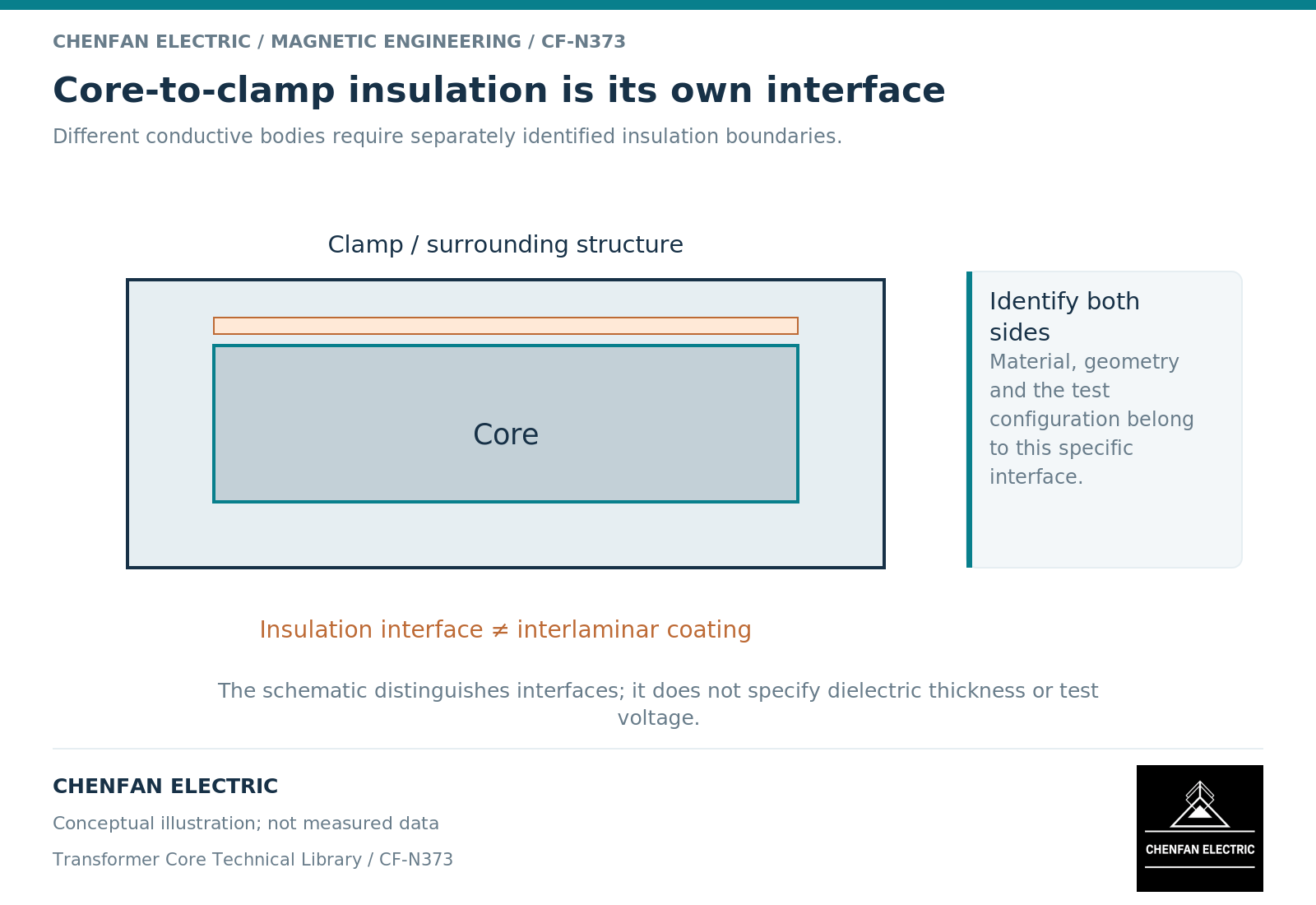
Draw three objects instead of one metal assembly
A useful conceptual model starts with a core node, a clamp node and a tank or support node. The design states which connections are intentional and which interfaces provide electrical separation. The mechanical arrangement then shows how those functions are maintained.
Core-grounding studies treat electrical potential and coupling through a defined network. [1] The same discipline applies here: a test described only as “core insulation” is ambiguous until the nodes and connected structures are named.
A clamp can remain mechanically associated with the core while being electrically separated at selected interfaces. Conversely, one support connection can defeat the intended separation without changing the dimensions of the insulating component itself.
Separate component evidence from assembly evidence
An insulating piece’s material specification supports its identity and relevant properties. A dimensional inspection supports its shape and fit. Neither alone proves the assembled core-to-clamp electrical boundary.
The insulation between laminations limits electrical circulation at a different scale. Lamination models distinguish bulk magnetic behavior, conductivity and the effects of an insulated stack. [2] These are not equivalent to the core-to-clamp node relationship.
| Evidence | Supported scope |
|---|---|
| Insulating component record | Material identity and specified component properties |
| Interface drawing | Intended separation, location and assembly relationship |
| Assembled electrical test | Identified node pair in a stated configuration |
| Lamination coating evidence | Interlaminar material or sample behavior |
| Final integration record | Boundary after added supports and active-part assembly |
Using separate names for these records prevents a familiar certificate from being applied to an interface it never evaluated.
Explain parallel paths before comparing results
Suppose the core and clamp are intended to be insulated from each other, but both remain connected to a common external node in the measurement configuration. The resulting reading may be dominated by that parallel route rather than by the interface under review.
This is a circuit-interpretation example, not an instruction to remove connections. The authorized test procedure must define the configuration that makes the desired measurement meaningful and safe.
Environmental conditions and the physical assembly state also belong in the comparison. A bare-core result before additional hardware is installed does not automatically describe the final active part. Record the revision and stage rather than comparing two unlabeled values.
Release the interface with its ownership
The core supplier and transformer original equipment manufacturer should agree who supplies the insulating parts, who assembles each boundary and who verifies it at the relevant stage. The responsibility can differ between loose laminations, pre-stacked packets and an assembled core.
The final interface record should contain the node identities, applicable drawing, approved criterion, actual evidence reference and unresolved exceptions. Do not invent a universal resistance limit or test voltage to make the record appear complete.
A precise interface definition makes subsequent changes easier to assess. Replacing a support, adding a restraint or revising a clamp can then be checked against an explicit electrical boundary rather than a general assurance that “the core is insulated.”
References
[1] Xiu Zhou and coauthors / Frontiers in Energy Research. Analytical modeling and calculation of core grounding current in converter transformer (2023).
[2] David Meeker. Finite Element Method Magnetics User Manual.