

Single-point core grounding establishes a defined electrical potential for the designated core assembly while avoiding unintended additional conductive paths through surrounding structures. It is not a substitute for the transformer’s protective earthing system. The first design task is therefore to identify what belongs to the core node and what must remain electrically separate from it.
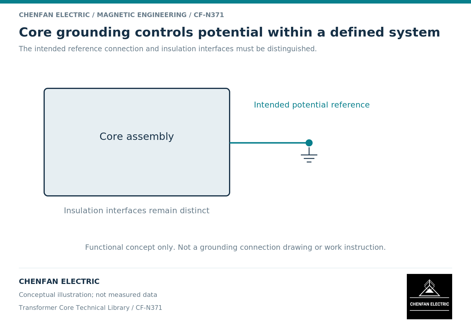
Define the node before counting connections
A core, its clamps, the tank and associated supports are not automatically one electrical object. Their intended connections and insulation interfaces must be defined by the transformer design. A drawing that shows one external ground lead can still conceal an unintended second path through hardware.
Research on converter-transformer core grounding distinguishes potential control from the capacitive paths that contribute to ground current. [1] The detailed arrangement in that research is not a universal wiring diagram for other transformer designs.
“Single point” should be interpreted against the designated electrical system, not as a rule to count every visible metal contact. A sectional or split assembly may need a deliberately defined internal continuity arrangement before it can be treated as one node.
Keep electrostatic and magnetic mechanisms separate
A conductive object near energized windings can acquire potential through capacitive coupling. A defined grounding arrangement controls that potential. Separately, a conducting loop linked by changing magnetic flux can develop an induced electromotive force. Faraday’s law explains the latter mechanism. [2]
These mechanisms can coexist, but they are not interchangeable. A ground-lead current may contain a capacitive contribution without proving an unintended magnetic loop. Conversely, the existence of a loop must be evaluated through its actual connections and linked field.
This distinction also explains why a zero current reading is not, by itself, proof that the intended ground connection is intact. Instrument limitations, operating state and an open measurement path all require consideration.
Make insulation boundaries visible
| Interface | Design question |
|---|---|
| Core to clamp | Is electrical separation intended here? |
| Clamp to tank or support | What continuity is required by the assembly design? |
| Core to designated ground lead | Which node and connection are identified? |
| Removable core sections | How is the final electrical grouping defined? |
| Monitoring or test interface | Which state is normal service and which is controlled testing? |
The answers belong in controlled drawings and procedures. A generic sketch is useful for discussing nodes, but it must not be mistaken for an installation or disconnection instruction.
The insulation system between individual laminations serves a different purpose and scale from the assembly-level core-to-clamp boundary. A lamination coating record does not establish that the completed assembly has only its intended ground path.
Verify the assembled state rather than a drawing symbol
The review should connect the electrical schematic, mechanical interface drawing and identified test record to the same assembly revision. Later-added supports, lead restraints or transport hardware can change the electrical network even when the core itself has not changed.
Any testing or change of grounding configuration requires the responsible original equipment manufacturer’s approved procedure and qualified personnel. This article supplies no test voltage, connection sequence or authorization to interrupt a ground.
The useful handover is a node map with intended connections, insulation boundaries, ownership and evidence references. That record supports both manufacturing and final integration without implying that a bare-core inspection approves the protective earthing or grounding condition of the complete transformer.
References
[1] Xiu Zhou and coauthors / Frontiers in Energy Research. Analytical modeling and calculation of core grounding current in converter transformer (2023).
[2] Lloyd Dixon / Texas Instruments. Magnetics Design 1 – Introduction and Basic Magnetics.