

Long-lamination placement accuracy depends on translation, rotation and part deformation. Measure the centre and both ends under working posture and payload to establish the error that reaches the step-lap features. [1]
Separate translation from rotation
Define the tool frame and the locations of the relevant lamination features within it. For a rigid part and small pose errors, the endpoint displacement is approximately the tool translation error plus the rotation-error vector crossed with the lever-arm vector. Rotation about an axis parallel to a particular lever arm produces a different endpoint effect from rotation across it.
The same angular error produces a larger transverse error as the feature moves farther from the rotation centre. Assess both ends and the relevant rotation axes; a tool-origin position check alone misses that amplification.
Measure the ends as well as the centre
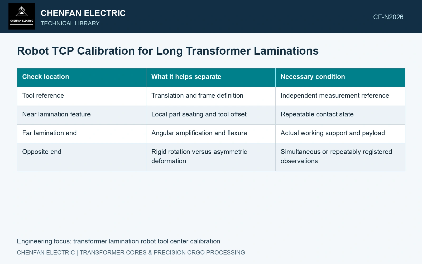
| Check location | What it helps separate | Necessary condition |
|---|---|---|
| Tool reference | Translation and frame definition | Independent measurement reference |
| Near lamination feature | Local part seating and tool offset | Repeatable contact state |
| Far lamination end | Angular amplification and flexure | Actual working support and payload |
| Opposite end | Rigid rotation versus asymmetric deformation | Simultaneous or repeatably registered observations |
Cover the postures used for picking, placing and withdrawal. NIST research distinguishes geometric offsets from position-dependent errors caused by loading, gravity and nonideal joint motion. A calibration performed with a light reference target may not describe the tool carrying a wide lamination at another posture. [1]
Measure accuracy and repeatability separately
Repeated placement can produce a tight cluster around the wrong location. Compare the mean placed feature with an independent target reference to assess accuracy, and assess the spread separately. The reference measurement has its own uncertainty, which must not be absorbed silently into a claimed robot error.
Check part seating in the gripper before assigning every endpoint discrepancy to the TCP. A variable suction contact or a different contact datum can move the lamination relative to an otherwise repeatable tool. A flexible part also cannot be described entirely by one rigid transform.
Nippon Steel’s nominal 0.23 mm gauge provides a useful geometric reference. [2] At the stated assumed 1 m lever arm, a 0.05° angular TCP error gives 1,000 sin(0.05°) = 0.873 mm transverse displacement, about 3.79 sheet gauges. Under an assumed 0.20 mm tip-position allocation, allowable angular contribution would be arcsin(0.20/1,000) = 0.01146° before other errors are allocated. Recalibrate orientation using a long-part witness and budget the remaining translation, compliance and vision errors; calibration at the tool origin alone misses the remote tip amplification.
Tool seating, orientation calibration, pad compliance and the actual part datum control remote-tip placement. Validate them over the working posture range used by the long lamination family.
Retain the error map by feature, posture, payload and tool configuration. Apply frame corrections within that verified range and investigate seating or flexure when endpoint variation remains.
References
- G. Qiao and B. A. Weiss, Industrial Robot Accuracy Degradation Monitoring and Quick Health Assessment, Journal of Manufacturing Science and Engineering 141, 2019. DOI: 10.1115/1.4043649.
- Nippon Steel Corporation, Grain-Oriented Electrical Steel Sheets, catalogue D004je, April 2020, specification and typical-property tables.