

Inspect a step-lap tip once gripper withdrawal reveals it, then verify that withdrawal has preserved its position. Pair visibility with physical stability to qualify the placement-and-release sequence.
Mark what the camera can actually see
Overlay the gripper outline on the intended inspection view at placement and during retraction. Identify the features needed for the decision: a cut edge, gap, tip or unique profile. Mark each as visible, partly visible or hidden at every relevant tool position.
A visible edge on the opposite side of the sheet does not automatically establish the position of a hidden flexible tip. Nor does a controller position establish where the tool’s physical outline appears in the image. Use the actual tool, working posture and lamination family to establish the observable area.
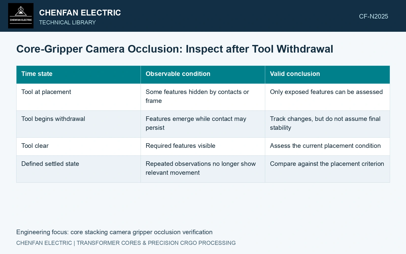
| Time state | Observable condition | Valid conclusion |
|---|---|---|
| Tool at placement | Some features hidden by contacts or frame | Only exposed features can be assessed |
| Tool begins withdrawal | Features emerge while contact may persist | Track changes, but do not assume final stability |
| Tool clear | Required features visible | Assess the current placement condition |
| Defined settled state | Repeated observations no longer show relevant movement | Compare against the placement criterion |
Register the image to the stack
Use stationary references in the inspection scene to separate camera vibration from part displacement. If the complete image shifts during robot withdrawal, an unregistered pixel difference can falsely indicate sheet movement. Record exposure timing and any frame-processing delay relative to actual tool motion.
Do not select a fixed wait solely because the robot’s program has reached a retract command. Determine the observation state from measured clearance and the relevant movement response. A long exposure can blur a transient shift; a single early frame can accept a tip that later slides.
Distinguish concealment from disturbance
Track a feature as soon as it becomes visible and compare it with the later clear view. If its position changes, investigate residual suction, tool contact, airflow or sheet settling as separate candidates. An unseen placement state cannot be reconstructed confidently from a later image without supporting observations.
NIST robot assessment research separates geometric and non-geometric tool-position/orientation errors from measurement uncertainty. Use that distinction to qualify the actual measurement chain; flexible-sheet shape and camera visibility still require their own application-specific evidence. [1]
Assume the final camera has a calibrated scale of 0.05 mm/pixel. A 0.23 mm nominal catalogue-gauge step spans 4.6 pixels when viewed normal to that feature. [2] If the gripper masks a 2 mm-wide region at the lap tip, it hides 40 pixels and potentially the full feature used for release. A confidence score from the visible edge cannot close that blind spot. Acquire the specified post-withdrawal view and verify its lighting, resolution and registration against the actual defect size before releasing the layer.
Camera pose, gripper withdrawal distance, tip support and sheet reflectivity govern observable geometry. Keep a physical occlusion challenge in the setup check rather than treating every software detection as a complete inspection.
Record the inspected features, the observation after tool withdrawal and the final position. Provide another view or measurement method for features outside the camera’s coverage.
References
- G. Qiao and B. A. Weiss, Industrial Robot Accuracy Degradation Monitoring and Quick Health Assessment, Journal of Manufacturing Science and Engineering 141, 2019. DOI: 10.1115/1.4043649.
- Nippon Steel Corporation, Grain-Oriented Electrical Steel Sheets, catalogue D004je, April 2020, specification and typical-property tables.