

A transformer-side fault can expose a sheath-voltage limiter to more than a brief voltage peak. Depending on the sheath circuit and fault duration, the device may absorb energy over a longer interval. Its duty cannot be judged from the maximum recorded voltage alone. [1]
Begin with the installed sheath circuit: cable sections, bonding links, grounds and limiter locations. The fault path establishes which limiter carries current and what voltage appears across it. A generic diagram from another feeder may not represent this arrangement.
Put voltage and current on one time base
Instantaneous device power is p(t) = u(t)i(t). Voltage u is in volts, current i in amperes and power p in watts. Absorbed energy over an interval is W = integral of p(t) dt, in joules, with voltage and current polarity defined consistently.
The integral requires simultaneous waveforms. Multiplying a peak voltage by a peak current can combine values that did not occur at the same instant. Multiplying RMS quantities without accounting for the actual waveform and conduction behavior can also misrepresent a nonlinear limiter.
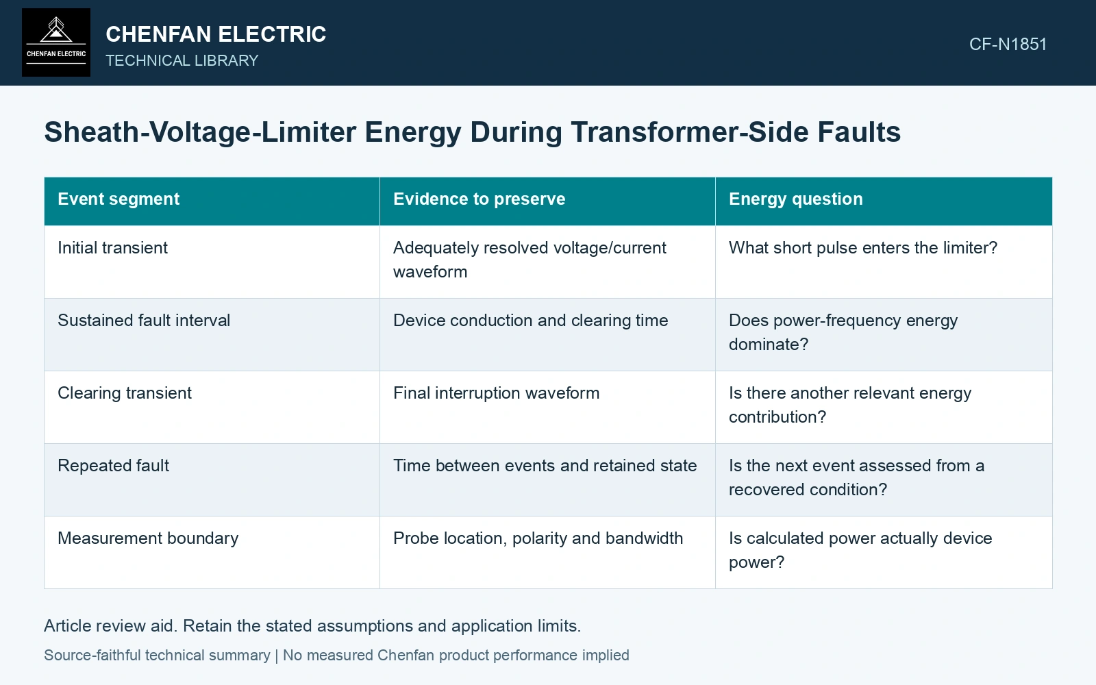
| Event segment | Evidence to preserve | Energy question |
|---|---|---|
| Initial transient | Adequately resolved voltage/current waveform | What short pulse enters the limiter? |
| Sustained fault interval | Device conduction and clearing time | Does power-frequency energy dominate? |
| Clearing transient | Final interruption waveform | Is there another relevant energy contribution? |
| Repeated fault | Time between events and retained state | Is the next event assessed from a recovered condition? |
| Measurement boundary | Probe location, polarity and bandwidth | Is calculated power actually device power? |
Model the limiter as part of the network
The voltage-current characteristic influences current flow, which in turn influences the sheath network. A calculation that prescribes both an arbitrary voltage and an arbitrary current can violate that coupling. Use the manufacturer’s verified characteristic within an appropriate transient or fault model.
Include grounding and bonding impedances relevant to the event. Their influence can redistribute duty among devices. If a route or link arrangement changed, reassess the limiter energy using the changed network rather than carrying the old result forward.
For metal-oxide devices, energy/charge withstand and thermal recovery have specified conditions. Richter explains that closely spaced surges accumulate and that cooling depends on construction, ambient temperature and applied voltage. Obtain the SVL’s own applicable record before selecting it for the sheath fault. [2]
Integrate the limiter energy at its terminals
Assumptions: a consistent sheath-network solution gives a rectangular terminal pulse of 1 kV and 100 A at the limiter. At 2 ms, W = 1000×100×0.002 = 200 J; at 5 ms, W = 500 J. Assume a device-specific qualification permits 350 J for this same waveform family, initial temperature and post-event applied voltage. The 2 ms case passes its energy screen with 150 J margin; the 5 ms case fails by 150 J. The corresponding energy-bound duration is 350/(1000×100) = 3.5 ms. Reject the 5 ms case and revise the sheath protection or limiter selection. This comparison still needs charge, residual-voltage and recovery checks against the SVL’s actual records. [2]
Compare like-for-like withstand evidence
A rated impulse energy or discharge-current value has test conditions. It cannot automatically represent a sustained fault duty with another waveform or duration. Preserve the manufacturer’s applicability statement and the operating condition used for the comparison.
References
- IEEE, IEEE 575-2014, IEEE Guide for Bonding Shields and Sheaths of Single-Conductor Power Cables Rated 5 kV through 500 kV (historical edition).
- B. Richter, Hitachi Energy, Metal-oxide surge arresters in medium-voltage systems: Application guidelines, sixth edition 2018, document 1HC0075561 EN2 AC, May 2022, sections 3.3–3.5.