

A feeder’s screen wires may carry only part of the earth-fault current, or they may carry a significant share through a particular section. The phase conductor’s short-circuit rating does not answer this question. The screen has its own area, material, connections and thermal limit. [1]
The analysis begins with current paths. Identify screens, sheaths, bonding conductors, earth connections and other parallel returns. Assign fault current using a model consistent with the actual network, rather than applying the total system fault current to every metallic path.
Preserve the current history
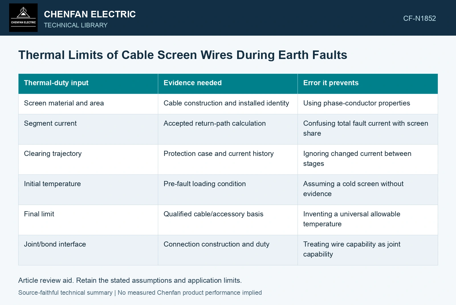
Fault clearing can include more than one stage. The current may change as sources or protective devices operate. Record the current in the screen segment through that sequence, including a credible repeated event where relevant. A single current-and-duration pair should be used only when it represents the assessed duty.
| Thermal-duty input | Evidence needed | Error it prevents |
|---|---|---|
| Screen material and area | Cable construction and installed identity | Using phase-conductor properties |
| Segment current | Accepted return-path calculation | Confusing total fault current with screen share |
| Clearing trajectory | Protection case and current history | Ignoring changed current between stages |
| Initial temperature | Pre-fault loading condition | Assuming a cold screen without evidence |
| Final limit | Qualified cable/accessory basis | Inventing a universal allowable temperature |
| Joint/bond interface | Connection construction and duty | Treating wire capability as joint capability |
Understand the adiabatic approximation
An adiabatic model assumes negligible heat leaves the conductor during the event. Electrical heat input is the time integral of i²R, while the material stores heat as its temperature rises. For a uniform section, resistance depends on temperature and geometry, so a realistic calculation uses appropriate material properties over the relevant range.
This reasoning leads to the familiar relationship between area and the square root of an i²t duty under specified assumptions. It does not supply a universal material constant or temperature limit. Those values must come from the accepted engineering basis for the cable and its construction.
IEC 60949 separates an adiabatic short-circuit calculation from the modifying factor for heat leaving the current-carrying component. Select the thermal model for the actual screen and adjacent construction; a steady-state ampacity calculation does not establish fault endurance. [1][2]
Compare fault duration using current squared
Assumptions: the assessed screen and its connections have a qualified common duty gate of 2.5×10⁶ A²s, at an initial 70 °C and the stated qualification final-temperature limit. For this screen path, 2 kA RMS for 0.5 s gives 2.0×10⁶ A²s and passes with 20% of the duty gate unused. A changed 3 kA RMS for 0.3 s gives 2.7×10⁶ A²s, exceeding the gate by 8%, despite faster clearing. Reject that revised protection case. Under the same adiabatic qualification basis, 3 kA must clear within 2.5×10⁶/3000² = 0.278 s. Recheck current sharing and actual initial temperature before using this bound. [1]
Check the weakest physical interface
A screen-wire calculation does not certify its termination, joint or bonding lead. Current can concentrate at a connection whose heat path differs from the distributed screen. Preserve those component boundaries and verify their relevant duty separately.
References
- IEC, IEC 60949:1988, Calculation of thermally permissible short-circuit currents, taking into account non-adiabatic heating effects.
- U.S. Department of Energy, DOE-HDBK-1012/2-92, Thermodynamics, Heat Transfer, and Fluid Flow, Volume 2, 1992.