

A cross-bonded cable route may contain three minor sections and still have imperfect induced-voltage cancellation. Their lengths can differ, their phase geometry can change and their sheath connections can follow an incorrect identity. Counting three sections does not establish the electrical result. [1]
The review should track each sheath segment through its actual route and connection. This is a calculation and documentation task; it is not an instruction to alter a live link box.
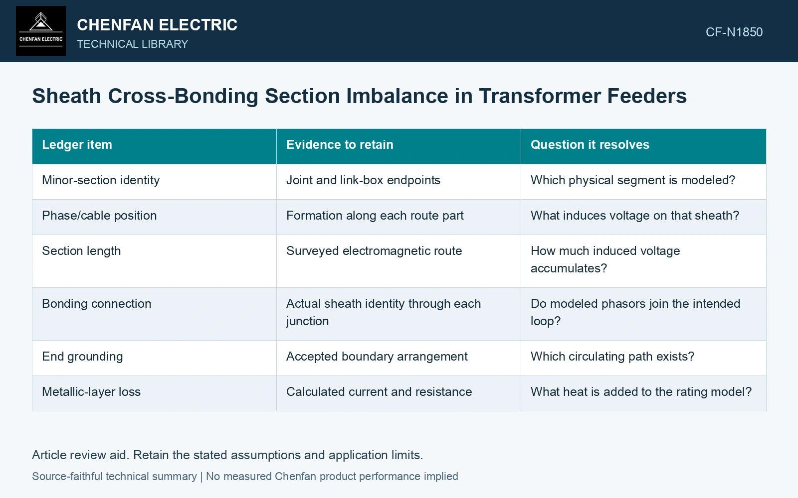
Build a section-voltage ledger
Induced sheath voltage depends on the phase currents and the electromagnetic geometry along the segment. Length is one factor, but cable spacing, arrangement and neighboring circuits also matter. A longer section in a different formation cannot always be represented by scaling the shortest section’s voltage.
| Ledger item | Evidence to retain | Question it resolves |
|---|---|---|
| Minor-section identity | Joint and link-box endpoints | Which physical segment is modeled? |
| Phase/cable position | Formation along each route part | What induces voltage on that sheath? |
| Section length | Surveyed electromagnetic route | How much induced voltage accumulates? |
| Bonding connection | Actual sheath identity through each junction | Do modeled phasors join the intended loop? |
| End grounding | Accepted boundary arrangement | Which circulating path exists? |
| Metallic-layer loss | Calculated current and resistance | What heat is added to the rating model? |
Use the ideal case as a diagnostic reference
In an ideal balanced arrangement, three equal induced-voltage phasors separated by 120 degrees sum to zero. If their magnitudes differ, their vector sum generally leaves a residual. Let E1, E2 and E3 be section voltage phasors in volts. The residual is their signed vector sum along the actual sheath path.
This statement assumes the relevant phasor directions and connections are known. It is not a complete sheath-network calculation. An actual loop includes impedance and grounding boundaries; the resulting current cannot be obtained from residual voltage alone without that circuit.
Separate three explanations for imbalance
Unequal lengths can create unequal accumulated voltages. Changed formation can alter induction per metre. Incorrect connection identity can defeat the intended cancellation even with equal lengths. Keep these hypotheses separate so an assessment does not blame every excess loss on civil route length.
Use the residual voltage with the closed sheath-loop impedance to obtain current; real loss follows I²R for that loop. Preserve phase directions when summing induced voltages, since their magnitudes alone cannot establish cancellation. [2]
Quantify imperfect sheath-voltage cancellation
Assumptions: cross-bonded section voltages are 100∠0°, 100∠120° and 110∠240° V RMS at 50 Hz. Equal 100 V components cancel, leaving a 10 V RMS residual. For an assumed closed-loop Z = 0.10 + j0.20 Ω, |I| = 10/√(0.10² + 0.20²) = 44.72 A and loop loss is I²×0.10 = 200 W. Ideal equal sections would produce 0 W from this residual mechanism. Against an assumed 150 W loss allowance for this modeled loop, the imbalanced arrangement fails by 50 W. Rework the section formation/bonding or rating assessment before approval; do not infer an allowable standing voltage from this loss gate. [2]
References
- IEEE, IEEE 575-2014, IEEE Guide for Bonding Shields and Sheaths of Single-Conductor Power Cables Rated 5 kV through 500 kV (historical edition).
- U.S. Department of Energy, DOE-HDBK-1011/3-92, Electrical Science, Volume 3, June 1992.