


Transformer Core Engineering Notes · CF-N245
Directed oil flow is intended to route pumped liquid through defined winding paths rather than leave its distribution mainly to the surrounding space. Its value depends on the actual internal arrangement and the resulting temperatures. A drawing with flow arrows or an ODAF label does not by itself prove that every relevant winding region receives adequate cooling.
Show the network and its assumptions
The model should identify inlet and outlet regions, winding ducts, parallel paths and possible bypasses. State the pump duty, fluid properties and boundary temperatures used. A simplified network can be useful if its assumptions are appropriate and validated; a detailed model is not automatically correct merely because it contains many cells. The reviewer needs to understand which physical features control the flow and how those features are specified for manufacture.
Connect flow to local heat generation
The heat source is not always uniform along or across a winding. Conductor losses, additional losses and connection regions can produce different thermal demands. The model must connect the loss distribution to the cooling distribution before predicting hot spots. Reporting only total oil flow and total transformer loss can hide an unfavourable local combination. State which temperatures are predicted and how the selected measurement or test evidence supports them.
Assess manufacturing variation and bypass
Duct dimensions, spacer positioning and guide installation can affect hydraulic resistance and distribution. Identify the tolerances that matter and the inspections that preserve the modelled paths. A missing or displaced internal guide may change performance without changing external pump readings dramatically. Treat these features as controlled thermal-design components. Any substitution that changes their geometry should be reviewed before release, rather than handled as an inconsequential assembly convenience.
Include unavailable equipment and off-design duty
Review the states the project expects to encounter, such as one cooling group unavailable, a different liquid temperature or a specified emergency load. Do not assume the normal flow pattern remains unchanged. The OEM should define permitted operation and any required protection or monitoring for those states. Directed flow is a design technique, not a promise of unlimited cooling margin or automatic redundancy when the driving equipment fails.
| Review item | Evidence to request | Boundary to preserve |
|---|---|---|
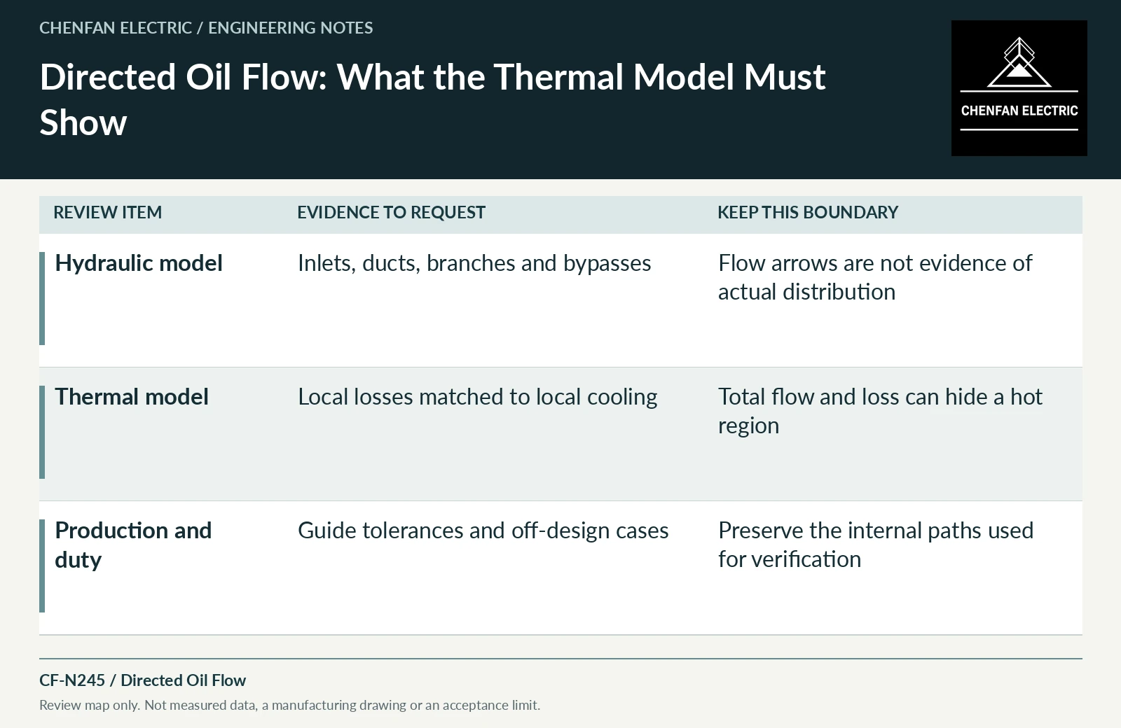
| Hydraulic model | Inlets, ducts, branches and bypasses | Flow arrows are not evidence of actual distribution |
| Thermal model | Local losses matched to local cooling | Total flow and loss can hide a hot region |
| Production and duty | Guide tolerances and off-design cases | Preserve the internal paths used for verification |
References and scope
- IEC 60076-2:2011 — Temperature rise for liquid-immersed transformersPublic standard abstract · Temperature-rise requirements, cooling identification and the distinction between test conditions and installed duty.
- IEEE C57.91-2025 — Loading Mineral-Oil-Immersed Transformers and Step-Voltage RegulatorsPublic standard abstract · Mineral-oil loading, thermal duty and loading beyond nameplate; do not transfer the scope automatically to ester or dry-type equipment.
- Optimizing transformer insulation systemsManufacturer technical page · Interaction of solid insulation, spacers, flow and mechanical support.