

A DC winding resistance test can leave magnetic remanence, while any preceding voltage applied across insulation can leave dielectric polarization or charge. These states are different. Whether the resistance test creates meaningful dielectric memory depends on its voltage path relative to other windings and earth. [1]
Reconstruct the preceding test connections rather than assuming every DC test stresses every insulation path. Mark terminals, grounded parts and disconnected windings. Retain source voltage, duration and the approved discharge or demagnetization actions actually performed.
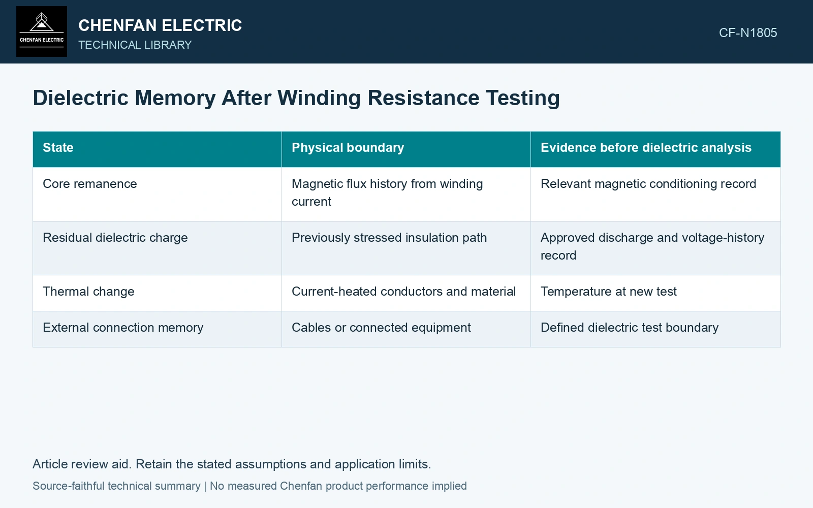
| State | Physical boundary | Evidence before dielectric analysis |
|---|---|---|
| Core remanence | Magnetic flux history from winding current | Relevant magnetic conditioning record |
| Residual dielectric charge | Previously stressed insulation path | Approved discharge and voltage-history record |
| Thermal change | Current-heated conductors and material | Temperature at new test |
| External connection memory | Cables or connected equipment | Defined dielectric test boundary |
Do not use one reset for both states
Demagnetization addresses a magnetic condition. It should not be represented as proof that dielectric charge is absent. Conversely, terminal discharge does not establish zero core remanence. Use the instrument and plant procedures for each relevant state.
A prescribed wait has a purpose, but elapsed time alone is not universal proof of a relaxed dielectric. Slow absorption and the actual insulation path can matter. This article supplies no waiting interval or discharge method.
Raxsa and co-authors represent dielectric relaxation with series RC absorption branches. Their state depends on which insulation terminals saw voltage and its prior duration; a magnetic demagnetization record does not specify those branch states. [2]
Model the relevant dielectric boundary
Assumptions: one prior test holds an identified winding at 100 V relative to earth and its effective terminal capacitance is 10 nF. Its lumped cross-insulation charge scale is CU = 1 μC. A 100 V source applied only from one end of that winding to the other instead specifies a differential terminal voltage; without its earth reference and distributed capacitances, the same 1 μC cross-insulation charge cannot be inferred. Hold a zero-initial-polarization assumption until the actual voltage paths and relaxation history are reconciled. Treat core magnetic conditioning separately. [1][2]
References
- U.S. Bureau of Reclamation, FIST Volume 3-31, Transformer Diagnostics, June 2003, section 16.2.
- J. Raxsa, P. Nimsanong, T. Mai-Eiam and P. Yutthagowith, Determination of Dielectric Models Based on Effective Multi-Exponential Fittings, Energies 16, 4615, 2023. DOI: 10.3390/en16124615.