

Moisture or contamination on a bushing surface can add a current path to a transformer dielectric measurement. A guard is intended to divert selected current from the measuring channel. Its connection must match the intended insulation boundary and the instrument’s supported arrangement. [1]
Draw the voltage source, measurement input, guard and protective earth as different nodes. Mark the intended internal insulation path and the surface path being excluded. An instrument with three labelled terminals does not establish that every proposed guard connection is valid.
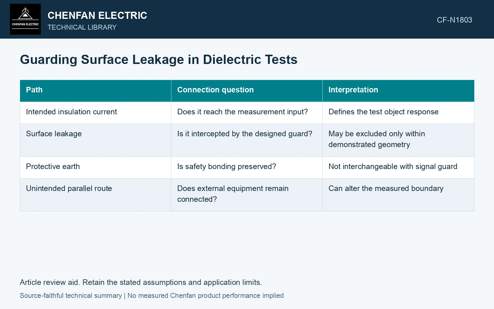
| Path | Connection question | Interpretation |
|---|---|---|
| Intended insulation current | Does it reach the measurement input? | Defines the test object response |
| Surface leakage | Is it intercepted by the designed guard? | May be excluded only within demonstrated geometry |
| Protective earth | Is safety bonding preserved? | Not interchangeable with signal guard |
| Unintended parallel route | Does external equipment remain connected? | Can alter the measured boundary |
Compare guard states only under an approved connection
A controlled comparison can show whether a surface path materially affects the result. Preserve voltage, temperature, object state and instrument settings. A changed curve does not automatically identify which excluded path was responsible.
Confirm that the guard has not excluded the insulation region the diagnosis intends to measure. A cleaner-looking curve can represent a different object rather than better data for the original one.
Arsad and co-authors describe guarding unwanted influence in the winding-to-winding dielectric measurement. The excluded contribution depends on that defined connection; guard and protective earth still have different functions. [2]
Quantify the excluded surface contribution
Assumptions: matched tests at 20 °C and 100 s after the same 500 V step show 30 nA unguarded and 18 nA in the guarded measuring channel. The excluded contribution is 12 nA, or 40% of the unguarded current; its voltage-normalized value is 24 pS. This single-time response is not automatically a steady DC leakage conductance. Accept the guarded result for the intended boundary only after the approved node/path map confirms that internal target current was retained. Do not identify a specific contaminated surface from the difference alone. [1][2]
References
- IEEE, IEEE C57.161-2018, IEEE Guide for Dielectric Frequency Response Test.
- S. R. Arsad et al., Water Content in Transformer Insulation System: A Review on the Detection and Quantification Methods, Energies 16, 1920, 2023. DOI: 10.3390/en16041920.