

Screen sustained overexcitation against the available magnetic-data range, then plan the local thermal assessment. Changed excitation can redistribute loss into joints and structures; identifying the governing temperature requires the actual source and heat-removal evidence. [1] [2]
Define the actual excitation duty and its duration. An average core-loss increase alone cannot identify which region becomes limiting or how quickly it approaches its temperature boundary.
Map the source under the changed excitation
Use winding voltage, frequency, active turns and waveform to establish the magnetic history. A sinusoidal voltage/frequency screen is useful within its assumptions; distorted or biased excitation requires the corresponding time-dependent calculation.
Recalculate local losses using data and formulations valid in the relevant field range. Do not extrapolate a low-induction loss curve into a high-demand region simply because the numerical solver accepts it. Check how nonlinear field redistribution changes joints, packet ends and nearby conductive structures.
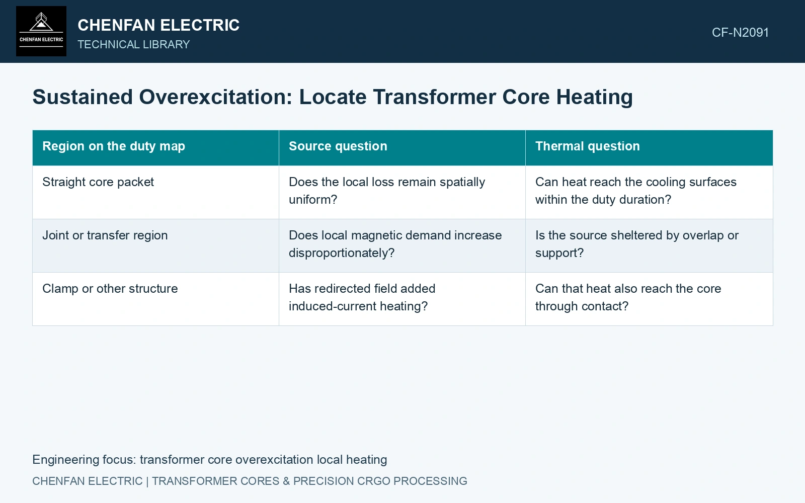
| Region on the duty map | Source question | Thermal question |
|---|---|---|
| Straight core packet | Does the local loss remain spatially uniform? | Can heat reach the cooling surfaces within the duty duration? |
| Joint or transfer region | Does local magnetic demand increase disproportionately? | Is the source sheltered by overlap or support? |
| Clamp or other structure | Has redirected field added induced-current heating? | Can that heat also reach the core through contact? |
Keep core and structural losses separate before coupling their thermal paths. A hot clamp is not a direct measurement of the steel loss beneath it.
Calculate from the actual initial temperature
Start the thermal model at the credible pre-duty state. A cold laboratory construction and a transformer already warm from load have different transient margins.
Apply the spatial heat input over the specified interval and allow for temperature-dependent properties where supported. Distinguish the temperature reached at the end of the duty from a hypothetical steady state. A short-time pass does not establish indefinite operation, while a steady-state model can miss a local transient response if its source or boundary history is wrong.
Check migration of the limiting location
Track temperature over the suspected regions and relevant surrounding fluid. The highest-loss location need not be the highest-temperature location if heat-removal paths differ. A sensor plan based solely on normal excitation can miss a newly limiting joint or shielded region.
Validate the applicable material response, loss formulation and thermal path through approved evidence. Where the specified duty lies beyond their coverage, identify the gap instead of reporting an exact predicted hot-spot value.
Nippon Steel’s quoted 23ZH90 loss condition is 1.7 T at 50 Hz. [3] Assume nominal sinusoidal peak flux of 1.60 T, then consider voltage at 1.05 per unit and frequency at 0.98 per unit with unchanged active turns and effective area. Peak flux becomes 1.60 × 1.05/0.98 = 1.714 T, above that catalogue loss condition. It is therefore invalid to retain the 0.90 W/kg value as an overexcitation prediction. Obtain magnetic and thermal evidence covering this duty, or revise the excitation envelope; extrapolating a strip point cannot establish local clamp or joint temperatures.
Effective steel area, joint gaps, overlap and clamping stress set the local magnetic margin. Carry their production bounds into the excitation check before using a nominal flux calculation to select a temperature-test duty.
Report the changed source, heat-removal path and controlling duration for each region. Tie the thermal assessment to the defined overexcitation cases and their supporting magnetic evidence.
References
- Z. Chen, Z. He and S. Wang, Transformer Iron Core Temperature Field Calculation Based on Finite Element Analysis, Energies 18, 6537, 2025. DOI: 10.3390/en18246537.
- U.S. Department of Energy, DOE-HDBK-1012/2-92, Thermodynamics, Heat Transfer, and Fluid Flow, Volume 2, 1992.
- Nippon Steel Corporation, Grain-Oriented Electrical Steel Sheets, catalogue D004je, April 2020, specification and typical-property tables.