

A core cooling duct can reduce the magnetic material within a fixed core envelope while creating a possible heat-removal path. A redesign can instead enlarge the envelope or rearrange packets to retain net steel area, so the area penalty is not universal. Assess the magnetic section and cooling path of the actual design together. More ducts do not automatically mean a cooler or more efficient core, because the reduced net area can increase magnetic excursion and the duct may not provide the assumed cooling flow.
Recalculate net magnetic area explicitly
The magnetic area must exclude nonmagnetic regions in a way consistent with the actual geometry and stacking definition. Do not deduct a duct twice if it is already excluded from the specified net area, and do not treat gross outline area as net steel area.
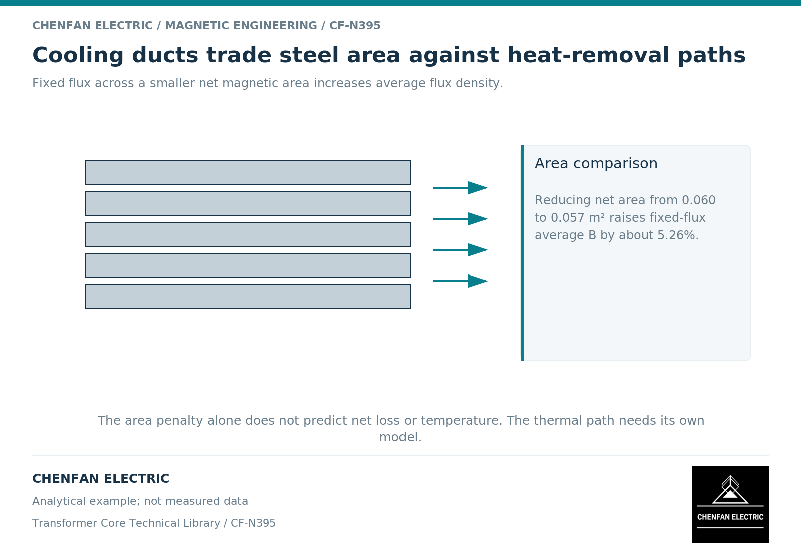
For a fixed flux, average flux density is flux divided by the relevant magnetic area. [1] As an illustrative calculation, reducing net area from 0.060 m² to 0.057 m² increases average flux density by about 5.26% if flux is unchanged.
That ratio is not a complete local-field prediction. The arrangement of packets, ducts and joints can make the field nonuniform, and local redistribution may require a more detailed model.
Define what cools the duct surfaces
A channel provides useful cooling only through the actual heat-transfer mechanism and surrounding flow. Its orientation, dimensions, inlet and outlet conditions, adjacent materials and operating medium matter.
Thermal modeling requires appropriate source terms and boundary conditions, not merely an empty region in the geometry. Finite-element documentation treats heat generation, material conduction and boundary transfer as separate inputs. [2]
If a calculation assumes a heat-transfer coefficient, record its origin and applicability. A duct drawn in a core does not prove that the same coefficient applies throughout it or under every operating condition.
Compare magnetic and thermal effects together
| Review quantity | Required basis |
|---|---|
| Net magnetic section | Packet geometry, ducts and stacking convention |
| Flux-density distribution | Excitation and local magnetic representation |
| Loss distribution | Material data and applicable waveform |
| Heat-transfer path | Actual medium, flow and interfaces |
| Maximum temperature | Location, duty duration and boundary assumptions |
| Mechanical integrity | Support and restraint around the duct arrangement |
A design with a lower thermal resistance can still have a higher temperature if the changed magnetic design produces substantially more heat. Conversely, an area reduction may be acceptable when the complete thermal and magnetic assessment supports it.
The comparison should use the same induced voltage, turns and frequency unless they are deliberately redesigned. Changing all three while attributing the result solely to the duct is misleading.
Release the duct as an integrated feature
The drawing should define the duct location, geometry, relevant insulating or spacing components and the associated net-area calculation. The manufacturing record should preserve these features without replacing them with a generic “cooling gap” note.
Validation should compare the appropriate temperature locations and operating cases. A bulk cooling-medium temperature does not directly verify the hottest internal packet; a surface measurement does not automatically establish the entire core’s thermal state.
For a core manufacturer, duct geometry and net area are linked requirements. For the transformer designer, the cooling environment and complete active-part integration remain essential. The practical decision is whether the selected duct arrangement improves the complete design within its magnetic, thermal and mechanical limits—not whether it simply contains more open space.
References
[1] Lloyd Dixon / Texas Instruments. Magnetics Design 1 – Introduction and Basic Magnetics.
[2] David Meeker. Finite Element Method Magnetics User Manual.