

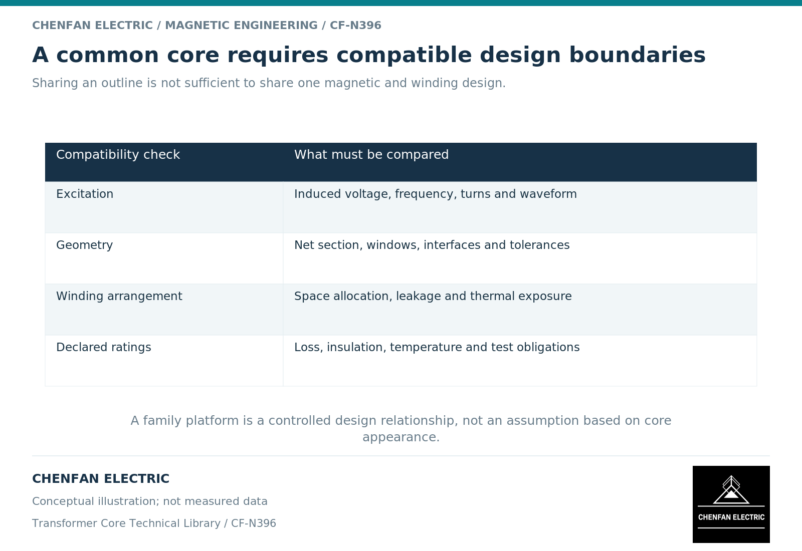
A common core can support more than one transformer rating only when every associated design remains compatible with its magnetic operating envelope and physical interfaces. Sharing a core part number may simplify procurement, but it does not establish that the windings, cooling system or complete transformer are interchangeable across ratings.
Check excitation independently of apparent power
Main flux is linked to induced voltage per turn, frequency, waveform and net magnetic area. [1] Apparent power alone does not determine it. Two transformers with different current ratings can therefore have similar main-core excitation, while two with the same apparent-power rating can impose different magnetic duties.
Compare active turns at every relevant tap, maximum induced voltage and minimum operating frequency. Include specified distorted or exceptional waveforms where applicable. A match at the nominal tap is not enough if the operating envelopes differ.
The shared core must be assessed against the most demanding compatible magnetic cases, not an average of the family members.
Treat the window as a shared constraint
Higher current may require a different conductor section, winding build or cooling arrangement. The same core window can become limiting even when the magnetic excitation remains unchanged.
Transformer design guidance links area, turns, window allocation and winding losses. [2] A common-core strategy must therefore compare the actual winding envelopes, insulation clearances, cooling passages and supports of each family member.
| Compatibility item | Evidence for each rating |
|---|---|
| Magnetic excitation | Voltage-per-turn and waveform envelope |
| Winding fit | Released winding and insulation arrangement |
| Leakage performance | Required impedance with actual winding geometry |
| Thermal duty | Core, winding and structural heat-removal assessment |
| Mechanical duty | Supports and relevant current-force cases |
| Manufacturing interface | Common and variant-controlled dimensions |
A repeated core outline does not make these other requirements common automatically.
Qualify the family through explicit cases
A useful family matrix identifies which design is most demanding for each observable. The highest-current member may govern winding heating, while another connection or tap range may govern excitation. A geometry variant may govern local structural exposure.
Do not assume one “largest rating” test represents every smaller rating. The evidence must explain why the selected cases bound the relevant differences. Where they do not, retain separate verification.
A common material specification also needs a defined substitution policy. Changing material within one family member can affect the common qualification argument even when the drawing remains unchanged.
Control common parts and variant assumptions separately
The core drawing should define the genuinely common manufactured object. A separate design record should identify the transformer variants that use it and the conditions under which that use was approved.
Changes to the common core require review across the affected variants. Changes to one winding may not require a new core drawing, but they can require renewed active-part electrical and thermal assessment.
For Chenfan Electric core supply, this approach supports repeatable manufacturing without turning a manufacturing commonality into an unsupported system-level claim. The commercial benefit comes from controlled reuse, not from relabeling one design for several duties.
The release conclusion should be specific: this core is compatible with these identified transformer designs under these evaluated conditions. That statement is both more useful and more defensible than saying that a core is suitable for a broad rating range solely because it fits the same external envelope.
References
[1] Lloyd Dixon / Texas Instruments. Magnetics Design 1 – Introduction and Basic Magnetics.
[2] Lloyd Dixon / Texas Instruments. Magnetics Design 4 – Power Transformer Design.