

A larger core diameter can increase the length of each winding turn while allowing a different turn count or magnetic operating point. The net effect on conductor length and winding loss depends on the coupled design. “Larger core means lower copper loss” is therefore not a reliable standalone rule.
Distinguish one turn from the whole winding
Mean turn length describes the average conductor path around the relevant winding geometry. Total active conductor length is approximately mean turn length multiplied by turns, with leads and construction details added as appropriate.
Transformer design guidance treats core size, window use, turns and winding losses as coupled variables. [1] A change in the core outline can also change insulation circumference, radial build and the positions of outer winding layers.
For a stepped core, the winding’s internal shape and clearances matter. The diameter of a circumscribing circle is not automatically the winding’s mean turn diameter, particularly for noncircular or layered constructions.
Compare two designs with the same constraints
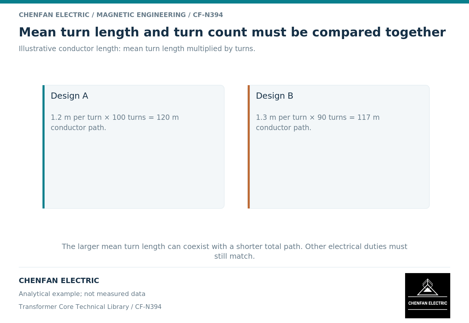
Suppose, illustratively, Design A has a mean turn length of 1.20 m and 100 turns, giving 120 m before leads. Design B has 1.30 m and 90 turns, giving 117 m. The second has longer individual turns but 2.5% less calculated conductor length.
This arithmetic does not establish that either design meets the same electrical duty. The revised turn count must be checked against induced voltage, frequency, net area and chosen flux density. [2] Ratio, tap range and regulation also remain constraints.
If conductor material, cross-sectional area and temperature were unchanged, direct-current resistance would follow the length ratio. If any of those quantities changes, resistance needs a new calculation. Alternating-current winding loss adds further geometry- and frequency-dependent effects.
Preserve the nonmagnetic consequences
| Changed design variable | Additional review |
|---|---|
| Core diameter or section | Net magnetic area and winding fit |
| Turn count | Voltage ratio, excitation and window occupancy |
| Mean turn length | Conductor quantity and resistance |
| Radial winding build | Leakage field and insulation arrangement |
| Cooling passages | Thermal performance and available conductor area |
| Core and winding mass | Support, handling and complete cost comparison |
A lower no-load core loss may be offset by a winding consequence, or the reverse. The comparison should retain both terms and the duty assumptions used to value them. It should not select only the favorable result from each incompatible design.
Geometrical improvements also need a manufacturable winding arrangement. A theoretical reduction in turns can be constrained by integer turns, conductor sizes, tap requirements and available insulation systems.
Report the coupled outcome
For each candidate, record core geometry, net area, active turns by tap, mean turn length, conductor section, relevant losses and thermal conditions. Mark which values are preliminary calculations and which are supported by released drawings or tests.
A sensitivity study can isolate the effect of diameter while holding other variables fixed. A design optimization can then vary them together within the required constraints. Keeping those two exercises separate prevents an apparent cause-and-effect claim from being based on several simultaneous changes.
For core procurement, the final diameter and step geometry are outputs of that coupled decision. They should not be revised independently by either party on the assumption that a larger or smaller core will always improve winding performance.
References
[1] Lloyd Dixon / Texas Instruments. Magnetics Design 4 – Power Transformer Design.
[2] Lloyd Dixon / Texas Instruments. Magnetics Design 1 – Introduction and Basic Magnetics.