

Fault debris rarely distributes itself evenly. Copper droplets may collect on a horizontal ledge, steel fragments can lodge between packet edges, and carbonized insulation can remain under a spacer after the visible window has been cleaned. A reusable core therefore needs a location-based cleanliness record, not just a photograph of its front face. [1]
The work begins with isolated equipment and a qualified repair method. The purpose of the map is to identify what must be inspected and verified. It does not authorize cleaning near energized conductors or prescribe a chemical treatment for an unknown coating system.
Follow the routes that debris can take
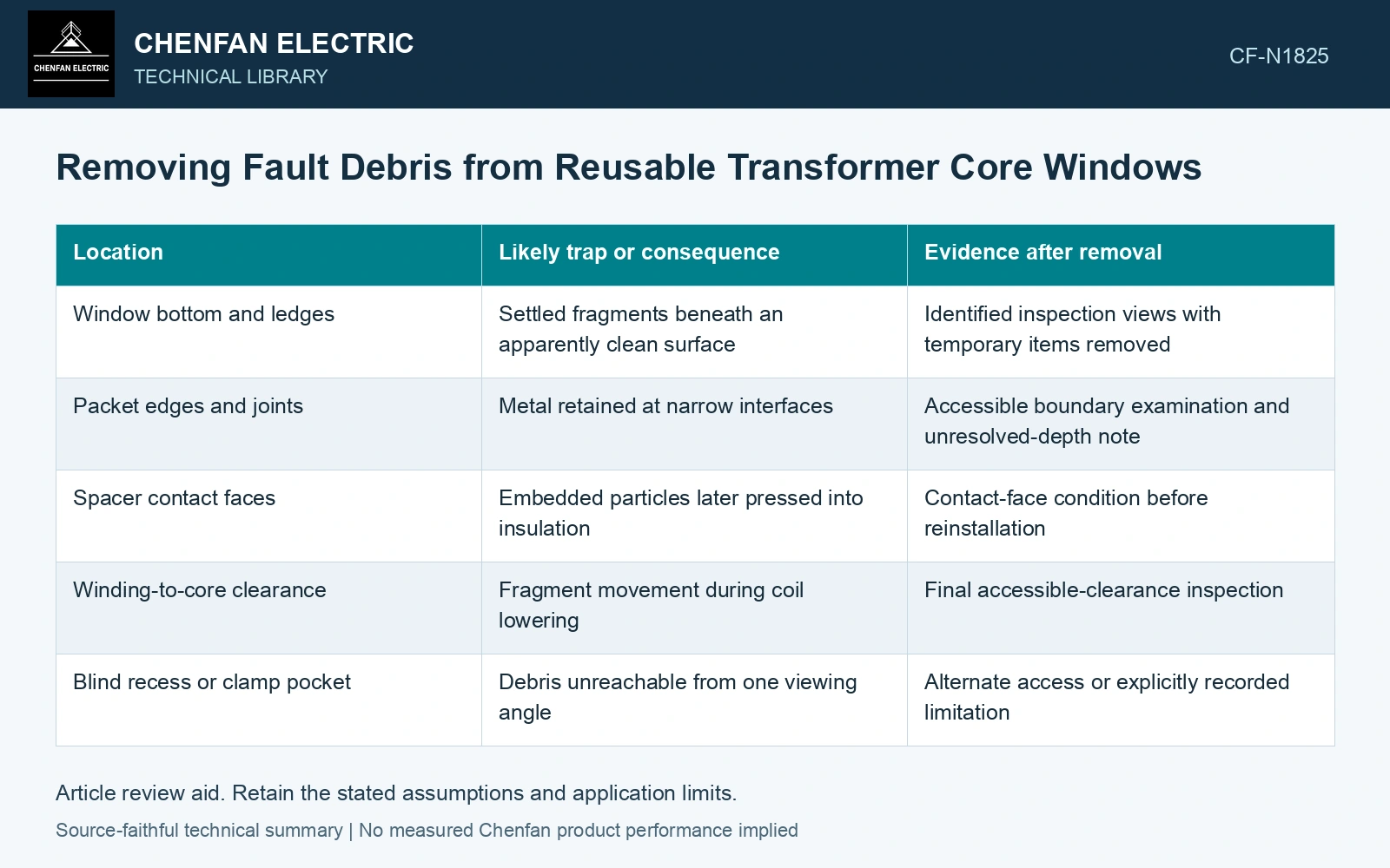
Use the fault location, gravity, accessible fluid paths and dismantling movements to identify plausible destinations. A fragment can move during winding removal and settle outside the original arc zone. Record that change: the debris map should describe the assembly being rebuilt, not only the assembly immediately after the fault.
Conductive fragments, carbonized material, fibers and cleaning residues create different concerns. A conductive piece can bridge electrical boundaries; a hard particle can damage insulation during reassembly; a retained fiber or deposit can obstruct a narrow passage. These are mechanisms to investigate, not proof that every recovered particle caused damage.
| Location | Likely trap or consequence | Evidence after removal |
|---|---|---|
| Window bottom and ledges | Settled fragments beneath an apparently clean surface | Identified inspection views with temporary items removed |
| Packet edges and joints | Metal retained at narrow interfaces | Accessible boundary examination and unresolved-depth note |
| Spacer contact faces | Embedded particles later pressed into insulation | Contact-face condition before reinstallation |
| Winding-to-core clearance | Fragment movement during coil lowering | Final accessible-clearance inspection |
| Blind recess or clamp pocket | Debris unreachable from one viewing angle | Alternate access or explicitly recorded limitation |
Cleanliness and damage are separate findings
Removing a fragment does not restore a scratched coating or a damaged insulating support. Record the underlying surface condition once the deposit is gone. Likewise, a solvent-compatible surface is not necessarily mechanically sound after scrubbing. The repair method needs to preserve the insulation and geometry that the assessment is trying to retain.
Before approving a method, identify its material compatibility, debris containment and residue verification. Where access is restricted, avoid equating a successful flush or wipe with confirmed absence of every trapped fragment. The verification must match the trapping location and the relevant particle or residue concern.
Test what the cleanliness method can actually exclude
For identified 23ZH85 source steel, Nippon’s catalogue thickness is 0.23 mm and density is 7.65 kg/dm³. [2] Assume a rigid fragment cut from that steel is 6 mm long and 1 mm wide. Volume is 6×1×0.23 = 1.38 mm³ and mass is 1.38×7.65 = 10.56 mg. Suppose the relevant electrical gap is 5 mm, the flush filter has a 2 mm square opening, and the residue-weighing method resolves only 20 mg. The 6 mm fragment can bridge the 5 mm gap if aligned, can pass end-first through the assumed opening, and is below the mass resolution. A clean filter/weight report therefore cannot close this trapping-location inspection. Require direct qualified inspection/removal at that ledge before release; do not substitute catalogue strip loss for debris evidence.
Particle removal, narrow-gap access, insulated fasteners and final clamp installation control the debris pathway. Preserve lamination coating and packet alignment while cleaning; an inaccessible ledge requires explicit final-state inspection evidence.
References
- U.S. Bureau of Reclamation, FIST Volume 3-31, Transformer Diagnostics, June 2003.
- Nippon Steel Corporation, Grain-Oriented Electrical Steel Sheets, catalogue D004je, April 2020, specification and typical-property tables.