

Establish the conservator’s actual liquid domain before calculating sloshing. NASA’s linear rectangular-tank method applies to a free surface [1]; a bladder or constrained interface needs another boundary model. Retain support and pipe movements separately [2].
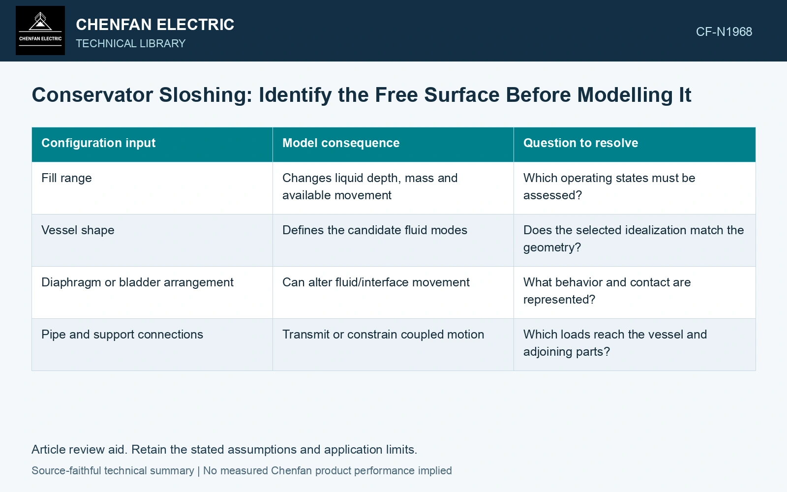
Draw the operating fluid configuration
Record vessel geometry, intended operating fill range, internal components and connected piping. Distinguish a freely moving liquid surface from an arrangement with flexible separation or other constraints. Do not assume a nominal oil volume provides a complete boundary definition.
| Configuration input | Model consequence | Question to resolve |
|---|---|---|
| Fill range | Changes liquid depth, mass and available movement | Which operating states must be assessed? |
| Vessel shape | Defines the candidate fluid modes | Does the selected idealization match the geometry? |
| Diaphragm or bladder arrangement | Can alter fluid/interface movement | What behavior and contact are represented? |
| Pipe and support connections | Transmit or constrain coupled motion | Which loads reach the vessel and adjoining parts? |
Separate impulsive motion from surface movement
Some liquid response follows the vessel motion more directly, while a free-surface component can have its own dynamics. A model should retain the mechanisms relevant to the actual configuration. Applying the entire liquid mass as one rigid lump cannot reveal surface elevation or local impact, while a free-surface-only model may omit other transmitted loads.
Evaluate possible regions of interaction with the vessel or internal parts where the chosen model predicts sufficient movement. A surface-elevation plot is a candidate for local assessment, not by itself a pressure or component-capacity result. The interpretation depends on the fluid model and its validated range.
Compare the fill states without changing the support assumptions
Use consistent support and input definitions when comparing fill levels. If one case uses a different vessel restraint or piping boundary, the difference cannot be assigned solely to liquid depth. Record damping and any simplification that limits the predicted fluid behavior.
Coordinate fluid-related loads with the conservator support assessment, keeping their timing or combination basis visible. Structural support resonance and sloshing are different mechanisms, although they can interact. A single frequency labeled “conservator mode” is insufficient when the model contains both.
Assume an unbaffled rectangular free surface L = 2.0 m, width 0.50 m, liquid depth h = 0.50 m and static freeboard 20 mm. Adding assumed 10 L raises mean level by 10 mm, leaving 10 mm. For small-amplitude ideal sloshing, k = π/L and f₁ = √[gk tanh(kh)]/(2π) = 0.506 Hz, period 1.98 s [1], with g = 9.81 m/s². Ensure the support-motion input covers this low-frequency mode; a high-frequency structural test may not exercise it. The remaining freeboard does not prove clearance to the wave crest. Obtain actual excitation/damping and evaluate surface movement/impact; replace this model if a bladder occupies the assumed open surface.
Identify which fill state produces each consequential fluid movement and where that movement interacts with the vessel or internal parts. Review those locations with the conservator connections. Sloshing frequency and impact pressure require the actual liquid domain and a model appropriate to it.
References
- H. N. Abramson (editor), NASA SP-106, The Dynamic Behavior of Liquids in Moving Containers, with Applications to Space Vehicle Technology, 1966, section 2.2, Rectangular Tank.
- FEMA and Applied Technology Council, FEMA E-74, Reducing the Risks of Nonstructural Earthquake Damage—A Practical Guide, December 2012, section 6.4.7.3, Transformers.