

Radiator banks have their own geometry, mass and connections. Bracing that appears effective in one plane may leave another direction flexible. The assessment should trace multidirectional motion into the braces, radiator attachments and tank rather than treating a braced elevation as proof of complete restraint. [1] [2]
Draw the three-dimensional restraint arrangement
Mark brace directions, attachment points, radiator mass distribution and connection stiffness. Identify the members that resist each translation and relevant rotation. Include the tank-side structures receiving the loads and any clearances that control engagement.
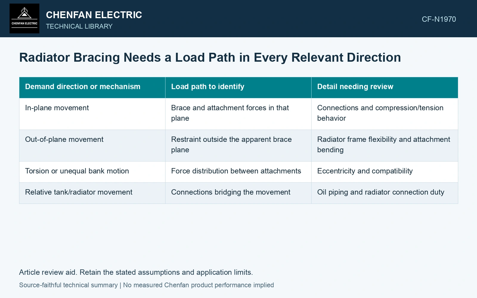
| Demand direction or mechanism | Load path to identify | Detail needing review |
|---|---|---|
| In-plane movement | Brace and attachment forces in that plane | Connections and compression/tension behavior |
| Out-of-plane movement | Restraint outside the apparent brace plane | Radiator frame flexibility and attachment bending |
| Torsion or unequal bank motion | Force distribution between attachments | Eccentricity and compatibility |
| Relative tank/radiator movement | Connections bridging the movement | Oil piping and radiator connection duty |
Oil piping is a connection, not a convenient spare brace
Check whether the structural model unintentionally transfers restraint through oil pipes or radiator valves. If those parts are expected to carry a mechanical demand, the design basis and connection assessment must establish it. A pipe that limits visible movement can still be carrying an unacceptable local load.
Brace placement should also be compatible with thermal movement, installation access and the actual pipe arrangement. A new diagonal can improve one structural path while obstructing a connection or adding restraint where movement is needed. Review those interfaces together.
Apply the chosen multidirectional assessment consistently
Use the input directions and combination method required for the project. Retain the corresponding force directions at each brace and tank attachment. Combining unrelated maxima without a stated method can distort the demand, while considering only one convenient direction can miss a governing response.
Evaluate the radiator assembly in the specified liquid and installation state. Historical damage and mitigation examples explain why braces and continuous load paths matter, but their dimensions and photographed configurations are not a ready-made design for another radiator bank.
Assume a brace carries a 20 kN horizontal load through a member inclined 30° to that load direction, with an ideal pin-jointed axial load path. Required member force is 20/cos(30°) = 23.09 kN and its perpendicular reaction is 11.55 kN. A brace selected for only 20 kN axial force is already short under this simple geometry. Check both reactions, compression buckling and the receiving radiator/tank attachments, then repeat for the other relevant direction rather than assuming a visible diagonal provides complete seismic restraint.
An unrestrained direction, an overloaded tank attachment and an oil connection acting as a brace require different corrections. Mark each against the three-dimensional layout and its calculated demand. The presence of a diagonal in one elevation does not resolve the remaining directions.
References
- FEMA and Applied Technology Council, FEMA E-74, Reducing the Risks of Nonstructural Earthquake Damage—A Practical Guide, December 2012, section 6.4.7.3, Transformers.
- IEEE, IEEE 693-2018, IEEE Recommended Practice for Seismic Design of Substations.