

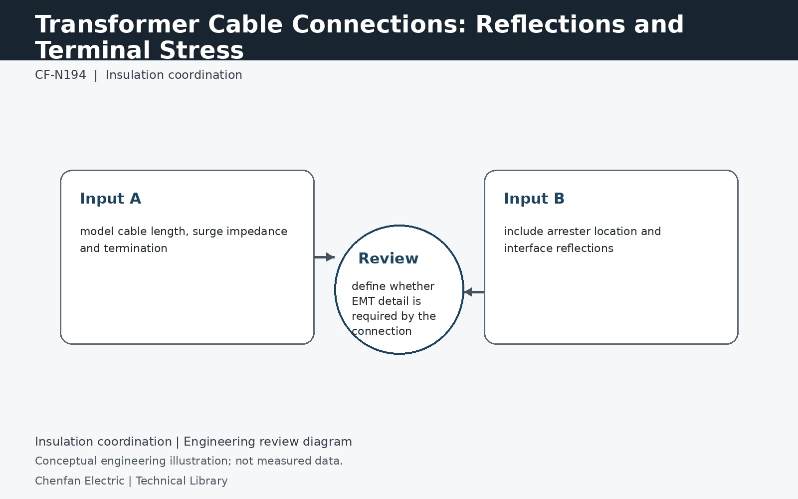
A cable-connected transformer sees travelling-wave behavior different from an overhead-line terminal. Cable surge impedance, length, termination, reflections at GIS or transformer interfaces and nearby arresters can change front steepness and peak voltage. Long or unusual cable connections may therefore require a transient study rather than assuming the standard terminal test alone represents all service stresses.
A reflection coefficient explains the first boundary effect
For a simple lossless line meeting a resistive termination, the voltage reflection coefficient is Γ = (Zt − Zc)/(Zt + Zc), where Zc is line surge impedance and Zt is termination impedance. At an ideal open end, Γ approaches +1 and the initial terminal voltage can approach twice the incident wave. A transformer is not a frequency-independent open circuit, so this limiting example must not be used as a blanket doubling rule for actual transformer terminals.
Cable length sets travel time as well as capacitance
A wave's one-way travel time is approximately length divided by propagation velocity; repeated reflections introduce intervals related to the round-trip time. Changing cable length can therefore shift the timing of wave superposition, not simply increase or decrease a lumped capacitance. Use cable construction and frequency-dependent data appropriate to the study range. A short connection may still be important for a sufficiently fast front, so “short cable” is not itself a justification for omitting propagation.
Check the winding interface, not just the cable rating
Retain the transformer terminal model, cable terminations, nearby arresters and their lead geometry. Compare peak voltage and front characteristics with the manufacturer's applicable insulation assessment. A cable and transformer can each meet their individual purchase standards while their combined switching interface still requires coordination. The handoff should identify the studied cable length and arrangement so a route change or different termination is not treated as an electrically irrelevant installation detail.
Technical reference framework
[1] IEC 60071-1:2019 — Insulation co-ordination, Definitions, principles and rules.
[2] IEC 60071-2:2023 — Insulation co-ordination, Application guidelines.
[3] IEC 60076-3:2013 + AMD1:2018 — Insulation levels, dielectric tests and external clearances.
[4] IEEE C57.98-2026 — Transformer impulse tests.